
- Fire Engineering Training

Elevators: Power Shunt Trip
Greg Havel discusses how an elevator’s power shunt trip, which is activated before automatic fire sprinklers discharge, could affect firefighting operations and how firefighters can deal with them.
Article and photos by Gregory Havel
The ASME and NFPA standards and codes consider the occupants of an elevator car that is stopped between floors or that is evacuated at the nearest floor level to be at less risk than they would be if the elevator continued to operate during fire sprinkler discharge.
3. Arriving firefighters may initiate Phase II Emergency In-car Operation by using a key and pressing buttons inside the elevator car to close and open doors and to move the car between floors. Photo 1 shows a typical lobby elevator control panel with the key switch to select firefighter operation. Photo 2 shows a typical elevator car control panel, with the firefighter key switch and indicator lights in the red panel in the center and operating instructions in red directly above. In this way, firefighters can quickly move equipment to upper floors nearer the location of the fire and evacuate persons who are unable to self-evacuate using stairways.
4. If smoke is present at the top of the elevator hoistway or in the machine room, the smoke detector will activate a circuit in the elevator controller. This will cause the red firefighter helmet indicator light on the control panel (see photos) to begin to flash, indicating that smoke and fire are near the elevator machine or in the hoistway and that a power shunt trip is possible. The instructions on the panel in Photo 2 state, “WHEN [fire helmet] FLASHES, EXIT ELEVATOR.” Firefighters at this time have the choice of manually opening the elevator doors at the nearest floor and exiting the elevator or attempting to return the elevator car to the primary recall floor with the risk of becoming trapped in the elevator between floors when the power shunt trip breaker operates.
5. When significant heat is present at the top of the elevator hoistway or in the machine room, the heat detector near a sprinkler head will sense that sprinkler discharge is imminent and will cause the main elevator power to shunt trip without delay, without any action by the elevator controller. This power shunt trip breaker can only be reset manually in the elevator machine room. Disconnection of the elevator main power does not affect lights or communications with the elevator car, which are on separate circuits.
However, there are two (rare) scenarios in which firefighters or other building occupants could become trapped by a power shunt trip:
- A very slow elevator, or one with a great distance to travel, with a fast-moving fire in or near the elevator machine room. In this instance, the elevator does not have time to complete Phase I recall before the power shunt trip.
- A large-scale incident in a multistory residential building occupied by many persons who are not capable of self-evacuating by way of stairs, which could result in firefighters using the elevator on Phase II operation to the last possible moment to remove as many occupants as possible.
The author acknowledges the valued assistance with the research for this article by Brian Rausch PE, at the Wisconsin Elevator Safety Program of the Wisconsin Department of Commerce.

- Download this article as a PDF!
- More Construction Concerns
- More Building Construction
- More Fire Prevention and Protection
Subjects: Building construction for firefighters
Related Posts

Latest Fire Engineering News

Please check your spam folder and any email filters, in the event that the email gets blocked.

Get the latest training and management insights for the fire service.

Compliance with the 2017 NEC for Elevator Controllers
Traditionally, the electrical system design engineer has given little attention to the elevator controller. In fact, an entire elevator system for a project is most often designed and specified by the architect who has little understanding of the electrical distribution system. Because of this, there is often a communications gap between the electrical system designer, whose design typically stops at the required elevator disconnecting means, and the architect who designs the elevator system. To address this issue, Code Making Panel (CMP) 12 of the National Electrical Code ® acted on several proposed changes to Article 620 during the revision cycle for the 2017 NEC that deal with the proper installation of elevator controllers.
The proposals resulted in adding new requirements in the 2017 NEC for:
- Marking the elevator controller short-circuit current rating (SCCR) by the elevator controller manufacturer.
- Reinforcing NEC 3 (B) and NEC 110.10 to require the elevator controller marked SCCR to be equal to or greater than the calculated and marked available short-circuit (fault) current at the elevator controller.
- Marking the available short-circuit (fault) current on the controller by the equipment installer.
This article will also discuss other Code requirements that include selective coordination for elevators that are supplied by emergency, legally required standby or critical operation power systems or multiple elevators supplied from a single feeder, and shunt tripping of elevators where the elevator equipment room and/or shaft has a fire suppression sprinkler system. Finally, typical installations and compliance with all these requirements will be discussed.
Equipment SCCR and short-circuit current marking requirements
The reason the NEC CMP 12 added these requirements, as shown in the panel statements, directly relates to the concern that elevator controllers can be installed in locations where the available fault current can be high and the inspector may not be able to clearly determine the SCCR of the elevator controller unless it is marked on the equipment. The panel further clarified that the marked SCCR value must be adequate for the available fault current to ensure a safe installation. In order to aid enforcement, the panel additionally required marking the available fault current at the elevator controller. Below is a summary of these new 2017 NEC sections:
- 620.16(A) Manufacturers must mark their elevator control panels with an equipment short-circuit current rating (SCCR). The SCCR can be based on an assembly product standard listing and labeling, or an approved analysis method, such as UL 508A, Supplement SB.
- 620.16(B) If the elevator control panel SCCR is not equal to or greater than the available fault current, the elevator control panel must not be installed.
- 620.51(D)(2) An elevator control panel must now be field marked with the maximum available fault current along with the date the calculation was made. Further, if there is a change to the available fault current, then this field marking must be revised.
Complying with these new requirements
In order to comply with these requirements a chain of events must occur.
- The electrical system designer calculates the maximum available fault current at the elevator controller.
- The electrical system designer needs to communicate this information to the person responsible for specifying the elevator controller, which is most often the architect.
- The party responsible for procuring the elevator control panel must state the minimum acceptable SCCR or the maximum available fault current where the controller will be installed.
- The elevator controller manufacturer must determine the required elevator controller SCCR as stated in the elevator controller specification and provide an elevator controller SCCR that is equal to or greater than the available fault current that’s indicated in the design documents where there are multiple elevator controllers at different locations.
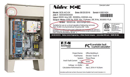
With these new NEC requirements, there is now the potential that an elevator controller SCCR may be required that’s higher than what elevator manufacturers have historically furnished. As such, elevator controller manufacturers should make the effort to rethink their designs to avoid costly system design changes. For instance, a typical elevator controller may traditionally have SCCR ratings from 5 to 10 kA. However, it is likely that for many elevator controllers, this may not be high enough for the available fault current where they will eventually be installed.
Some elevator controller manufacturers believe this is an issue for the electrical system designer and installer to address and remedy by adding impedance to the system for lowering the available fault current. This, however, can result in a dramatic increase in cost, space availability (lack thereof), and reduced efficiency. For instance, one method to reduce the available fault current is to add an isolation transformer ahead of the elevator controller.
Many new buildings are incorporating an elevator design that does not include an equipment room (sometimes called machine room-less elevators). All equipment in a machine room-less design is installed within the elevator shaft or exterior compartment near the elevator shaft, including the elevator controller and the elevator disconnecting means. In these installations, it is best to design the elevator controller so the elevator controller SCCR is adequate for the available fault current. This is something that can be easily accomplished if the elevator controller manufacturer uses components in combination with overcurrent protective devices that are tested and listed with high combination SCCRs. In many cases, the overcurrent protective devices that are suitable for this level of protection are current-limiting fuses rather than a traditional circuit breaker. In this case, it may be best if the elevator controller manufacturer does not include the elevator disconnecting means (often offered as a circuit breaker) but instead have the installer provide a separate fused disconnect to comply with NEC 620.51(A) and also achieve a high SCCR for the elevator controller when fuses are provided as specified by the elevator controller and marked on the elevator controller nameplate.
Selective Coordination
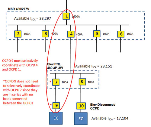
If elevators are supplied by the emergency, legally required standby or critical operation power systems, then selective coordination is required per the 2017 NEC in 700.32, 701.27 or 708.54. Selective coordination is also required for multiple elevators per NEC 620.62. Another important electrical system design consideration for supplying power to multiple elevators is NEC 620.62. NEC 620.62 requires the elevator disconnecting means (fused switch or circuit breaker) to selectively coordinate with all supply-side overcurrent devices. Selective coordination is defined by the NEC as: “Localization of an overcurrent condition to restrict outages to the circuit or equipment affected, accomplished by the selection and installation of overcurrent protective devices and their ratings or settings for the full range of available overcurrents, from overload to the maximum available fault current, and for the full range of overcurrent protective device opening times associated with those overcurrents.”
In order to comply, the electrical system designer must determine the maximum available fault current at the elevator disconnecting means and assure the elevator disconnecting means overcurrent protective device will clear any overcurrent condition, up to the maximum available fault current, before any upstream overcurrent devices will operate. Notice the definition mentions the full range of operating times. This is important as the tradition of using only time-current curves for the analysis of overcurrent device operation is usually not sufficient since the time-current curves traditionally stop at 0.01 second (not time “zero”).
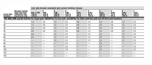
For current-limiting fuses, the information to achieve selective coordination has been available for many years in fuse amp ratio tabular form. These selective coordination tables for current-limiting fuses show the minimum amp ratio required between a pair of fuses of a given type(s) to achieve selective coordination.
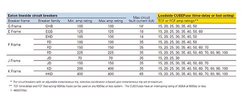
For circuit breakers, time-current curves must be consulted as well as the circuit breaker manufacturer’s selective coordination tables. These circuit breaker selective coordination tables can be used to identify the maximum fault current that a pair of circuit breakers can selectively coordinate. It is important to note, that these selective coordination tables can indicate a lack of selective coordination at a given fault current for circuit breakers that do not show overlap on the time-current curves of the circuit breakers. For some manufacturers, such as Eaton, testing has been completed to determine the selective coordination ability of current-limiting Bussmann TM series fuses with upstream Eaton circuit breakers.
Shunt Tripping
Where the elevator shaft and/or equipment room has a sprinkler fire suppression system installed, the elevator Code requires main line power to the elevator be removed prior to the application of water. This is typically accomplished via a shunt trip device.
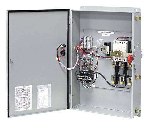
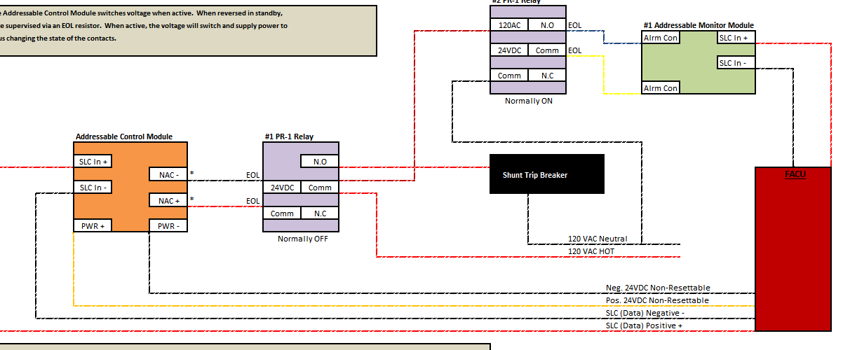
There are options available to achieve this depending upon the customer’s needs. The simplest option is to use a shunt trip circuit breaker in either the feeder supplying the elevator or the elevator disconnect. For elevators with battery lowering systems, an additional contact must be supplied and wired to disable the battery lowering system when the elevator disconnect is manually operated for maintenance. NFPA 72 requires the control circuit between the Fire Alarm System and the shunt trip be monitored for integrity. In addition, the shunt-trip voltage must also be monitored by the Fire Alarm System. Loss of voltage to the control circuit for the disconnecting means shall cause a supervisory signal to be indicated at the control unit and required remote annunciation. In some cases, it may require a means to test the shunt trip operation or have one contact operate the shunt trip of more than one elevator. Per the 2017 NEC , if the elevator is designated as an emergency system load, the disconnect must be protected by a surge protective device (SPD). All of these options and special wiring can be challenging depending upon the location of the shunt trip circuit breaker as well as who has responsibility for providing these additional options. Because of this, several manufacturers offer an all-in-one shunt trip elevator disconnect switch that includes all the prewired accessories needed to comply with the various Code sections.
Typical Elevator Installations
The architect has a choice of either traction or hydraulic elevators. Traction elevators are typically faster and more energy efficient than hydraulic elevators, and are often used for high-rise buildings. Hydraulic elevators are typically more cost effective and used for buildings up to 5-6 stories. Traction elevators are typically installed in a “bank of elevators” where fused switches, or circuit breakers in a panelboard are located in the machine room serving the bank of elevators. Each fused switch or circuit breaker in the panelboard is used as an elevator disconnect. Hydraulic elevator installations are typically supplied from the main switchboard and have an elevator fused switch or circuit breaker in the machine room that serves as the elevator disconnect.
As mentioned, traditional installations of a traction or hydraulic elevator include a separate machine room. The vast majority of equipment serving the elevator is located within this room (i.e., elevator controller). Also located in this room might be, but not limited to: exhaust fan, cooling unit (depending on local requirements and/or requirements set forth by the individual elevator supplier), lighting, voice and/or data drop serving the elevator cab emergency phone, elevator controller primary fused disconnect, elevator feeder shunt-trip circuit (i.e., shunt-trip circuit breaker), elevator cab lighting fused switch, and convenience receptacle(s).
Machine room-less elevator installations incorporate the elevator controller and often the primary disconnecting means in a convenient package that is located within the elevator shaft. However, space is frequently limited within the shaft and as such many ancillary components (shunt trip circuit breakers, fused disconnects) may need to be located outside of the elevator shaft. It is important for design engineers to communicate this with the architect and owner during the design phase, as it will impact space needs elsewhere in the facility to accommodate electrical equipment.
A traditional elevator installation (which includes a machine room) requires access inside the elevator shaft. Convenience receptacles and lighting for maintenance purposes are required at the base of the pit and, in some instances (elevator manufacturer dependent), at the top of the elevator shaft. It is important for the design engineer to coordinate with the architect to determine the elevator manufacturer basis of design to determine if and when additional power and lighting is required.
It is of great importance for the design engineer to communicate with their local authority having jurisdiction (AHJ) to determine fire alarm requirements for the respective elevator installation. While machine room-less designs have been commercially available for many years, their use may still be unknown to some AHJs. Design practices that are acceptable in some jurisdictions may not be in others. As always, the best advice in all instances…do your homework, communicate often, and document decisions made. Years may lapse between the design and installation stages of a project. Good documentation is of key importance to recalling what decisions were made and why.
With the new elevator controller requirements, more attention will be focused on the elevator system. First, it is now clear that elevator controllers must be marked by the manufacturer with their SCCR. The design engineer must identify the available fault current at the elevator controller to the installer so an elevator controller with adequate SCCR can be provided. If this is not done and the available fault current exceeds the elevator controller SCCR, other solutions to reduce fault current must be reviewed or equipment changes and field evaluations may be needed. In addition, requirements for selective coordination and shunt tripping should be complied with as needed for the installation.
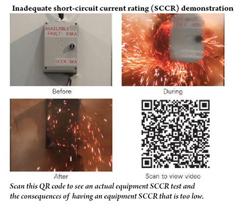
What are the Safety Hazards of Inadequate SCC
The hazards are external to the equipment enclosure since equipment SCCR testing and evaluation criteria for product standards are most often performed with the enclosure doors closed and latched, and the fault occurring external to the enclosure. Installing electrical equipment where its SCCR is less than the available short-circuit current creates serious safety hazards. These may include:
- Shock: The enclosure becomes energized from conductors pulling out of their terminations or device destruction occurring within the enclosure.
- Fire: The explosive power of the internal devices failing causes the closed and latched door to become ajar and spew flame and molten metal to the exterior. This is a fire hazard to both the facility and personnel.
- Projectile (shrapnel): The enclosure door may blow open or off with fire and failing device debris (shrapnel) shooting out. In laboratory tests, equipment SCCR failures have resulted in enclosure doors explosively blowing off and flying up to 100 feet away. Additionally, the shrapnel, from the rapid failure of internal devices, can be ejected at speeds up to 700 miles per hour.
The author would like to recognize Jonathan Kennedy for his assistance in creating this article.
Air-Conditioning Equipment Installations

Basic three-phase power measurements explained

Safety in Marinas

Find Us on Socials
Raceway connections.
As an installer and an inspector, one common issue I've seeen is incompatible connections associated with raceways connections and fittings.

Safety After the Storm — Operating Portable Generators
Electricity is often one of the initial services to fail during a storm. Many people use portable generators until power is restored.

22 Ways to Make Members Feel Valued
Here are 23 ways that both chapters and the national office can meet today’s major challenge of making members feel valued

The #1 website for NICET Practice Tests, NICET study guides, Fire Alarm Code Knowledge, and General Fire Alarm Topics. We have up to date information on the newest fire alarm trends such as fire service access elevators, mass notification, voice intelligibility, occupant evacuation elevators and two-way communication for Areas of Refuge. Topics also include fire alarm system programming and technical tips. Learn how to build the best ground fault meter with step by step instructions.
- NICET Exam Practice Test
- Bluebeam for Fire Alarm Design
- Occupancy FA Requirements
- 520 HZ Low Frequency Audible Tone
- Industry Links
- Conduit Bending
Saturday, December 17, 2016

How to Wire Elevator Shunt Trip
Elevator shunt trip wiring.
Looking for terminal crimping machine ? Then we are the best for you, who suit your expectations. We have huge experience on this field. We are 100% dedicated to find you terminal crimping machine. We are dedicated to manufacturing and sales of a wide range of terminal crimping machines including pneumatic crimping tool for crimp clamps. You can find here your best one. If you want to know more, Please check out Cheers Electronic Technical Co., LTD: https://www.terminal-crimping.com/

Galvin Power is reader-supported. When you buy via our links, we may earn a commission at no cost to you. Learn more
What is a Shunt Trip Breaker and How Does It Work?
Written by Edwin Jones / Fact checked by Andrew Wright
What is a shunt trip breaker? Does it add protection to your electrical system?
The shunt trip breaker is a combination of the shunt trip accessory and the main circuit breaker. This installs on the main breaker to add protection to your electrical system. This adds security to your electrical system as it manually or automatically cuts the electric supply in your circuit.
This accessory can help prevent short circuits and avoid electrical damage should a disaster occur in your home.
Let me tell you more about the shunt trip breaker to help you decide if you need additional protection for your electrical system.
Table of Contents
What is Shunt Trip Breaker and How Does It Work
Where are shunt trip breakers most used, how to install a shunt trip accessory to the breaker.

You should know that shunt trip breakers are different from GFCI circuit breakers.
The GFCI circuit breaker contains one big white tail wire for neutral connections only. It cannot be connected to any control package because the GFCI circuit breaker is solely designed to detect a sudden electrical surge. It has no other purpose but to cut power in case of a short.
Meanwhile, the shunt trip breaker wiring comprises two wires. One connected to the ground, and another to a control system. The control system can be connected to a sensor or to a manual switch. When activated, the shunt trip accessory will cause the main breaker to trip.
For example, if you install a shunt trip with a smoke detector, it will activate and cut off the power should the smoke sensor trigger. It can also be installed with a remote switch , allowing you to trip your breaker manually.
It is crucial to know the difference between a regular circuit breaker and a circuit breaker installed with shunt trip accessories.

The shunt trip definition means that it is a way to cut off electrical power through other sensors, not just via thermal activation. Since this is an optional accessory for a circuit breaker, it is not required for a home electrical system.
However, it is recommended for added safety. This is especially true if you’re working with industrial machinery. Furthermore, you can use it as a manual emergency switch to shut down your main breaker.
Before installing a shunt trip, consider its cost and your existing system. You may need to change the breaker panel and circuit breakers, especially if it is not compatible with shunt trips. You may also need a new line to connect the remote emergency switch to your breaker box.
Generally, most commercial kitchens, elevators, and offices have this shunt trip breaker because it is required. Commercial kitchens use this device in compliance with ANSI/ASME CSD-1, while elevators and escalators comply with ASME A17.1. These codes refer to the controls and safety standards provided by ASME’s.
This question is a topic of discussion among Reddit members as well. Join the conversation here:
Found at a dominos by u/Guilty_Sympathy_496 in electricians
Mostly, installing a shunt trip relay requires that the breaker and the shunt be from the same maker. Also, not all breaker models are compatible with this accessory.
Once you’re sure that your system can take a shunt trip accessory, installation is pretty much straightforward. You can watch this video by Aaron CBIONE for some tutorials.
Note: Every circuit breaker comes with different instructions. It would depend on the brand and model of the breaker .
However, the critical part of every installation is that you need to connect the shunt to your sensor. You may need a shunt trip breaker diagram as a reference to ensure correct installation.
Also, check the brand and model of your breaker before proceeding with the installation. Some makers only allow a factory install of the shunt trip and other accessories. DIY installation may void the warranty of your breakers. It’s best to read up on the manual or consult an electrical professional before making any changes.
What is a shunt trip breaker? The shunt trip is an optional accessory for a circuit breaker for added protection to your system. It is designed to connect to a secondary sensor. It will trip the breaker automatically if the sensor is triggered. It can also be activated via a remote switch that you can install.
Do you think that a circuit breaker is enough to protect your investment? Or do you want an additional layer of protection for your electrical circuit? If you’re not decided yet, reach out to me in the comments section below, and I will be happy to help you.

I am Andrew Wright. With 8 years of experience designing, installing, and maintaining electrical power systems. I love my job, and I have always wanted to offer others the necessary help so they can take care of their houses.


What Is A Shunt Trip Breaker & How Does It Works?
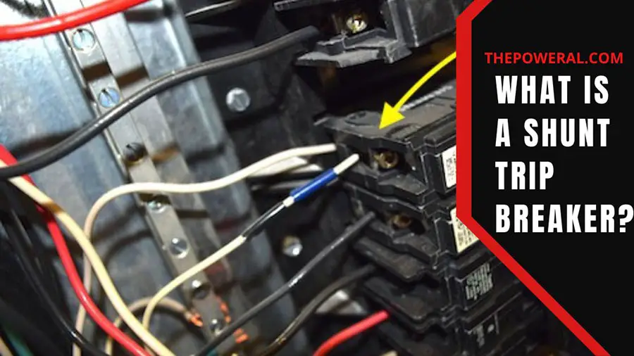
Have you ever heard about this kind of breaker? And “what a shunt trip breaker is” usually appears when you hear about this for the first time.
Keep this article to get the best answer to the question above, its primary use, and when it is required.
Table of Contents
What Is A Shunt Trip Circuit Breaker?
A circuit breaker “trips” once it detects a problem, cutting off power to the outlet or appliance in question and protecting the wire from burning.
An optional attachment to any circuit breaker, a shunt trip breaker allows for the breaker to be shut off remotely at any moment or immediately in the event of a power excess. Damage to or injury from equipment may be avoided in a crisis if this is in place.
There are two distinct categories for shunt trip breakers, automatic and manual. The breaker may be turned off from the exterior of the building through a remote button using manual switches. Conversely, mechanical switches interrupt power flow when they identify a surge coming from the grid.
How Does A Shunt Trip Breaker Work?
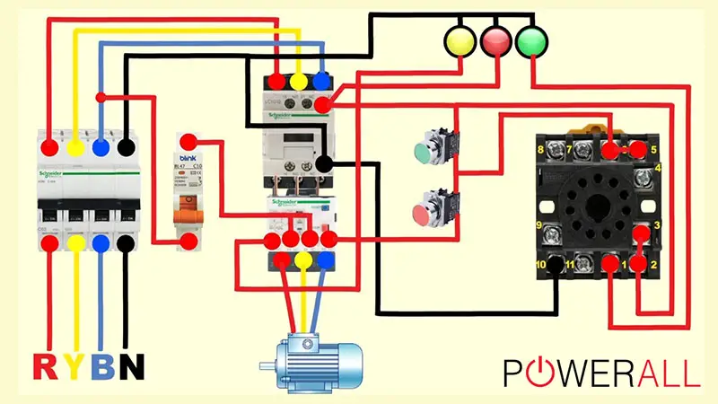
Electrical impulses often pass through your circuit breaker without being altered. Nevertheless, if these currents reach unsafe levels, an additional surge of energy will charge a magnet located just below the primary breaker switch. This will cause the switch to trip, resulting in the power being cut off.
Adding a shunt trip breaker provides an additional method to charge the magnets and trip the switches, which makes it possible to turn off the electricity remotely or automatically.
Some of the shunt trips are powered by an external source. When a power surge occurs at this source, a notification is delivered from the shunt trip towards the breaker, which causes the breaker to stop the power automatically.
Connecting to a remote switch that is situated outside the building may also be accomplished with the help of a shunt trip. The current is cut off when the user clicks a button on that switch, which causes an electrical surge to be sent via the shunt trip circuit.
Even though shunt trip breakers are optional in residences, many people put them there out of caution. But, these devices are also often used in businesses that use expensive industrial machinery or electronic wiring that are susceptible to being destroyed in the event of a power surge.
Why Are Shunt Trip Breakers Important?
In an unexpected power outage, you may give yourself an additional level of peace of mind by installing a shunt trip breaker in your house. Because of this, you will not risk injuring yourself or creating any electrical harm.
If there is a fire, one of the most common uses for shunt trips is to switch off any electrical equipment that could be present. For example, when a shunt trip is connected to a fire detection system, the power may be immediately turned off once the smoke detector senses a fire. This allows for eliminating any potential electrical hazards that the fire may cause.
If your smoke detector is connected to your home’s sprinkler system, installing a shunt trip is essential. This device might turn off your power as quickly as the smoke detector triggers the sprinkler, reducing the real damage to your electronic devices.
Where Do People Most Often Use Shunt Trip Breakers?
Shunt trips reduce power through additional sensors, not simply heat activation. For a household electrical system, this circuit breaker attachment is optional.
However, it’s advised for safety. Industrial equipment makes this particularly true. It may also shut off your main breaker manually in an emergency.
Before beginning the implementation of a shunt trip, take into consideration the associated costs and the system. It is possible that the breaker panel and the circuit breakers will need to be replaced if shunt trips are not supported. It’s also possible that a new cable will be required to connect the remote emergency switch to the breaker box.
In most business kitchens, elevators, and offices, shunt trip breakers are an essential safety device. ASME A17.1 is the standard that must be adhered to for elevators and escalators, while ANSI/ASME CSD-1 is the standard that must be attached to commercial kitchens. ASME regulations mandate these controls and safety standards.
Installing A Shunt Trip Accessory to a Breaker
Shunt trip relays can only be installed with breakers and shunts made by the same company. Plus, not all circuit-breaker models can use this part.
Adding a shunt trip connection is easy after establishing that your system is functioning. Watch this video from Schneider Electric for some guidelines:
Each circuit breaker has its instructions, so please follow them carefully. In addition, the make and model of the breaker are relevant.
The most critical step when setting up a sensor is to attach the shunt. If you want to be sure your shunt trip breaker is installed correctly, a shunt trip breaker diagram may be required.
It’s essential to verify the model and manufacturer of your breaker before commencing the installation. The manufacturer in some instances can only install the shunt trip and any other components. If you install your circuit breakers on your own, you might void the warranty. If you want to make alterations, you need either consult the manual or an electrician.
Here are some questions and answers related to the shunt trip breaker:
Does Shunt Trip Breaker Work?
Shunt trip breakers serve a vital purpose in the electrical system as a whole by providing an extra layer of protection for the circuits they are part of. In addition, they cut off electricity in times of crisis to avoid harm and damage to equipment.
What Are 3 Types Of Shunt Trip Breakers?
- Standard breakers
- Around fault circuit interrupter circuit breakers (GFCIs)
- Arc fault circuit interrupter circuit breakers
They are the three fundamental circuit breaker types (AFCIs). And standard breakers include both single-pole and double-pole circuit breakers.
Why Is Shunt Used In MCCB?
Molded case circuit breakers (MCCBs) are often employed in electrical distribution systems to prevent overload and short circuits from damaging electrical components. In reaction to a voltage signal from the outside, the shunt release device, a built-in component of MCCB, releases the mechanism.
You have completely got the answer to what a shunt trip breaker is and understand its function.
A circuit breaker’s shunt trip is an extra layer of safety that may be installed if desired. It’s meant to link up with another sensor. If the sensor is activated, the breaker will trip immediately. You may also set up a remote switch to turn it on and off.
- Why does my breaker keep tripping with nothing plugged in?
- Crouse hinds compatible breakers
- Challenger breaker replacement

Erik Watkins
Automotive Mechanic at PowerAll
With 7 years experience in management positions leading automotive mechanics at PowerAll, Erik Watkins wishes to share useful knowledge and information about automotive mechanical equipment.
Submit a Comment Cancel reply
Your email address will not be published. Required fields are marked *
Save my name, email, and website in this browser for the next time I comment.
Submit Comment

What Is A GFCI Outlet Receptacle? What Does It Stand For?

Gas vs. Electric Lawn Mower: Is Battery As Good As Gas?
Extension Cord Gauge/Length Chart: Amp Rating & Size

Dimmable LED Flash: LED Light Bulbs Flickering Solutions

Crouse Hinds Compatible Breakers & Replacement Chart

What Size Wire For 40 Amp Circuit Breaker?

- Forum Listing
- Marketplace
- Advanced Search
- General Electrical
- General Electrical Discussion
Elevator Shunt trip power circuit
- Add to quote
We have always had a seperate circuit for the power to the shunt trip for the breaker that supplied the elevator. I have seen where someone has tapped into this same circuit to supply other equipment. Is it not required for the elevator shunt trip circuit to be on its on seperate circuit since it is to be monitored by the fire alarm system? I have looked at NEC 2020 620 and do not see it there. I am not sure if it is in the NFPA 72.
Elevator Shunt Trip Requirements and Codes
- ?
- 97.3K members
Top Contributors this Month

IMAGES
VIDEO
COMMENTS
Elevator Shunt Trip is a function that involves the fire alarm system via heat detectors, shunting the breaker that controls the elevator equipment (typically set to activate 5 degrees before the actual automatic sprinkler head pops.). This in turn powers down the elevator equipment before any automatic sprinkler water is released.
not to shunt trip the breakers feeding the elevator. The shunt trip process is controlled by the Smoke and Heat detectors installed in the elevator shaft itself tied to the shunt trip breakers, not from the auxiliary contacts in the elevator service disconnect. Someone more knowledgeable about such will probably chime in. JAP>
The elevator's main power shunt trip breaker will trip and stop the elevator car wherever it is, even between floors, so that it will not malfunction when the sprinkler discharges. This power ...
The simplest option is to use a shunt trip circuit breaker in either the feeder supplying the elevator or the elevator disconnect. For elevators with battery lowering systems, an additional contact must be supplied and wired to disable the battery lowering system when the elevator disconnect is manually operated for maintenance.
typically accomplished via a shunt trip device. There are options available to achieve this de-pending upon the customer's needs. The simplest option is to use a shunt trip circuit breaker in either the feeder supplying the elevator or the elevator dis-connect. For elevators with battery lowering systems,
In this video I show the most common way I've seen elevator shunt trip setup and wired. I explain the concept behind elevator shunt trip and then explain how...
The shunt trip is an essential safety feature that allows for remote shut off of the power to the elevator in case of an emergency or malfunction. The wiring diagram provides a visual representation of the electrical connections and components involved in the shunt trip system. It includes various elements such as circuit breakers, relays ...
Below are some key points as well as code/standard references to assist you in understanding the basics of elevator recall and elevator shunt trip with fire alarm systems. 1st Floor Elevator Lobby Smoke Detector (activates alternate level recall sending the elevator to the second floor) NFPA 72 2016 21.3.13.2.
In one method below, we are using an addressable relay module (FRM-1) to operate the shunt trip breaker directly. With this wiring method, only the wire to the FRM-1 (SLC) needs to be supervised. This is obviously achieved through the SLC and addressing of the device. In the alternate method, we are showing you how to properly wire up the ...
In this video I show the utilization of a Cooper Bussmann Power Module Switch which dramatically simplifies elevator shunt trip. You'll no longer need to two...
@WARHAMMERELECTRIC Today We will be going over how to do a shunt trip breaker There are many steps to this but as long as you remember you have to keep both ...
The shunt trip breaker is a combination of the shunt trip accessory and the main circuit breaker. This installs on the main breaker to add protection to your electrical system. ... Commercial kitchens use this device in compliance with ANSI/ASME CSD-1, while elevators and escalators comply with ASME A17.1. These codes refer to the controls and ...
Chapter 30 Elevators and Conveying Systems Section 3006 - Machine Rooms 3006.5 -Shunt Trip. Where elevator hoistways or elevator machine rooms containing elevator control equipment are protected with automatic sprinklers, a means installed in accordance with NFPA 72, Section 3-8.15, Elevator Shutdown, (now 6.15.4) shall be provided
The ASME A17.1 Safety Code for Elevators and Escalators, Rule 102.2(c)(3), requires the shutdown of power to the elevator prior to the application of water in the elevator machine room or hoistway. (Figure 1, Note 2). Shutdown of power is usually accomplished with the use of a shunt trip device in the elevator circuit, and is done for two valid ...
Elevator Shunt Trip - Fire Alarm Requirements. 3-9.4.1* Where heat detectors are used to shut down elevator power prior to sprinkler operation, the detector shall have both a lower temperature rating and a higher sensitivity as compared to the sprinkler. 3-9.4.2 If heat detectors are used to shut down elevator power prior to sprinkler ...
In most business kitchens, elevators, and offices, shunt trip breakers are an essential safety device. ASME A17.1 is the standard that must be adhered to for elevators and escalators, while ANSI/ASME CSD-1 is the standard that must be attached to commercial kitchens. ASME regulations mandate these controls and safety standards.
1. The initiating devices (heat detectors) and shunt-trip will need to be tested. Generally, this is done during your annual building confidence testing. A fire/life safety contractor will test the heat and smoke detectors. A Class 1 electrician is needed to test the shunt-trip. 2.
Mersen's Fusible Shunt Trip Switch is an all-in-one solution that meets many different code requirements with the protection and safety in elevator shafts. According to NFPA 13, 9.3.6, sprinkler protection is required for hydraulic drive elevators and mechanically driven elevators, using combustible materials, at the top and bottom of ...
Elevator Shunt Trip is a function that involves the fire alarm system via heat detectors, shunting the breaker that controls the elevator equipment (typically set to activate 5 degrees before the actual automatic sprinkler head pops.). This in turn powers down the elevator equipment before any...
Shunt Trip Breaker on Elevator. Thread starter jimmyjam; Start date Dec 12, 2010; Status Not open for further replies. J. jimmyjam Member. Dec 12, 2010 #1 Can anyone give me information on wiring a shunt trip breaker with 120 volt coil. I think the 24 volts from the fire alarm system will tie to a 120 volt relay with 24 volt coil and when the ...
The fire alarm system will use low voltage communication circuits out in the field, and programmable relays within 3' of the elevator breaker to activate the shunt. This absolutely is an elevator question. In my experience, the shunt trip should be activated by sprinkler flow, not the fire alarm or smoke detector.