- Answers to Science Questions
- Archaeology
- Earth Science
- Engineering

How does light travel through glass?
Part of the show do animals use toilet paper, wine-glasses.

I believe that light is considered to be both waves and particles. My understanding is that particles are physical objects. If that is true, how is light able to travel through glass? Is it just the light waves that travel through glass or can the particles also penetrate glass?
The first thing is that any solid object that looks solid to us is actually has huge amount of space in it...
Even in an atom, the nucleus of the atom is about a hundred thousandth of the size of the actual atom. So there's immense amounts of empty space only containing electrons, which are even smaller than the nuclei, so there's lots and lots of space for things to travel through, as long as it doesn't interact with the nuclei or electrons.
A light wave is actually quite big compared to the size of an atom. It's a quantum mechanical object - it's kind of a particle, but it's kind of a wave. You can think of it as wave which only arrives in particles - not really something with which we have a handle on.
It's a lot easier to think of it as a wave in the circumstance. The only way to stop a wave is with something which will actually absorb it or scatter it, and in something like glass there's just nothing there which will absorb or to scatter it. So it just carries on going in a straight line.
Addendum for clarity:
Light is an electromagntic wave; that means that it comprises a changing electric field, which produces a changing magnetic field, which produces a changing electric field and so on... This is how the light propagates through space.
When light rays interact with an entity, like a piece of glass, the electromagnetic wave causes the electron clouds in the material to vibrate; as the electron clouds vibrate, they regenerate the wave. This happens in a succession of "ripples" as the light passes through the object. Because this process takes time, that's why light slows down slightly in optically more dense materials like glass.
Different colours of light have different frequencies; light that is visible to us passes through glass because the arrangement of the atoms in glass means that they can sustain the ripple effect described above at those frequencies, so light can pass through.
But other materals, with a different configuration of atoms in the crystal structure, cannot permit light to propagate and instead absorb the energy. A good example of this is an X-ray. It will go straight through a human body mostly unchanged, but the lead apron worn by the radiographer stops it in its tracks.
- Previous Are there materials that convert heat directly into electricity?
- Next What is the smallest thing that is possible to see with a microscope?
Related Content
Revolutions in light, the tell-tale hum, electrifying history, why what you see is not what you get , light pollution: time to flick the switch, add a comment, support us, forum discussions.

Snell's Law Calculator
Table of contents
When light travels from one medium to another, it bends or refracts. The Snell's law calculator lets you explore this topic in detail and understand the principles of refraction. Read on to discover how Snell's law of refraction is formulated and what equation will let you calculate the angle of refraction. The last part of this article is devoted to the critical angle formula and definition.
Snell's law of refraction
Snell's law describes how exactly refraction works. When a light ray enters a different medium, its speed and wavelength change. The ray bends either towards the normal of two media boundaries (when its speed decreases) or away from it (when its speed increases). The angle of refraction depends on the indices of refraction of both media:
- n 1 n_1 n 1 is the refractive index of medium 1 (from which the ray travels);
- n 2 n_2 n 2 is the refractive index of medium 2 (into which the ray travels);
- θ 1 \theta_1 θ 1 is the angle of incidence - the angle between a line normal (perpendicular) to the boundary between two media and the incoming ray;
- θ 2 \theta_2 θ 2 is the angle of refraction - the angle between the normal to the boundary and the ray traveling through medium 2.
🔎 You can check how the speed of light can change in different media in the wave velocity calculator .
You can find some of the values of n 1 n_1 n 1 and n 2 n_2 n 2 for common media in the index of refraction calculator .
Generally, Snell's law of refraction is only valid for isotropic media. In anisotropic ones, such as crystals, the ray may be split into two rays.
Finding the angle of refraction - an example
Let's assume you want to find the angle of refraction of a light beam that travels from air to glass. The angle of incidence is 30°.
- Find the index of refraction of air. It is equal to 1.000293 1.000293 1.000293 .
- Find the index of refraction of glass. Let's assume it is equal to 1.50 1.50 1.50 .
- Transform the equation so that the unknown (angle of refraction) is on the left-hand side: sin ( θ 2 ) = n 1 sin ( θ 1 ) n 2 \sin(\theta_2) = \frac{n_1 \sin(\theta_1)}{n_2} sin ( θ 2 ) = n 2 n 1 s i n ( θ 1 ) .
- Perform the calculations: sin ( θ 2 ) = 1.000293 sin ( 30 ° ) 1.50 = 0.333 \sin(\theta_2) = \frac{1.000293 \sin(30\degree)}{1.50} = 0.333 sin ( θ 2 ) = 1.50 1.000293 s i n ( 30° ) = 0.333 .
- Find the arcsin of this value: θ 2 = arcsin ( 0.333 ) = 19.48 ° \theta_2 = \arcsin(0.333) = 19.48 \degree θ 2 = arcsin ( 0.333 ) = 19.48° .
- You can also save yourself some time and simply use the Snell's law calculator.
Critical angle formula
Sometimes while applying the Snell's law of refraction, you will receive the sin ( θ 2 ) \sin(\theta_2) sin ( θ 2 ) as a value greater than 1. This is, of course, impossible. If this happens, it means that all light is reflected from the boundary (this phenomenon is known as the total internal reflection). Our Snell's law calculator will advise you when this happens.
The highest angle of incidence, for which the light is not reflected, is called the critical angle. The refracted ray travels along the boundary between both media. It means that the angle of refraction is equal to 90°. Hence, you can find the critical angle by using the following equation:
After simplification, n 1 sin ( θ 1 ) = n 2 ⋅ 1 n_1 \sin(\theta_1) = n_2 \cdot 1 n 1 sin ( θ 1 ) = n 2 ⋅ 1 .
Solving for the angle of incidence, θ 1 = arcsin ( n 2 n 1 ) \theta_1 = \arcsin(\frac{n_2}{n_1}) θ 1 = arcsin ( n 1 n 2 ) .
🙋 Thirsty for more knowledge? Check our De Broglie wavelength calculator to read about the wave-particle duality, which explains light refraction.
What is Snell's law?
Snell's law , or the law of refraction , describes the relationship between the angles of incidence θ₁ and refraction θ₂ and the refractive indices ( n ₁, n ₂) of two media: n ₁sin(θ₁) = n ₂sin(θ₂). The law of refraction allows us to predict the amount of bend when light travels from one medium to another .
Does Snell's law apply to all waves?
Yes , you can apply Snell's law to all isotropic materials , in all phases of matter . This happens because Snell's law is related only to the propagation of the wave and not to the details of the wave itself. Therefore, it works for sound waves as well.
What will be the angle of refraction if the angle of incidence is 10°??
7.5° . Let's say a light beam enters the water at 10° . To find an angle of refraction:
- Find the refractive indices of air, n ₁ =1, and water, n ₂ = 1.33.
- Solve Snell's law equation for θ₂: sin(θ₂) = n ₁sin(θ₁)/ n ₂. Therefore, θ₂ = arcsin(1×sin(10°)/1.33) = 7.5°.
How can I calculate the refractive index of the glass using Snell's law?
Assuming that light travels from air to glass , the angle of incidence is 30°, and the angle of refraction is 20°. To calculate the refractive index, follow these steps:
- Identify the refractive index of air: n ₁ = 1.
- Modify Snell's law to find the refractive index of glass: n ₂ = n ₁sin(θ₁)/sin(θ₂).
- Enter data : n ₂ = 1×sin(30°)/sin(20°) = 1.46.
What are the limitations of Snell's law?
The limitation of Snell's law of refraction is when light falls on the surface of the separation of two media normally or through a normal (perpendicular line). This is because when light falls through the normal, the angle of incidence θ₁ is equal to zero . Hence from Snell's law, sin(θ₁) = sin(0°) = 0 , and the angle of refraction is also equal to zero .

© Omni Calculator
Refractive index 1 (n₁)
...of medium 1.
Refractive index 2 (n₂)
...of medium 2.
Angle of incidence (θ₁)
Angle of refraction (θ₂)
Reset password New user? Sign up
Existing user? Log in
Snell's Law
Already have an account? Log in here.
- Andrew Ellinor
- Rishik Jain
- Someguy Noname
Snell's law , also known as the law of refraction , is a law stating the relationship between the angles of incidence and refraction, when referring to light passing from one medium to another medium such as air to water, glass to air, etc.
Explanation
Refraction through a glass slab, lateral displacement and it's calculation, normal shift, total internal reflection, effects and applications of total internal reflection, snell's law - problem solving.
Snell's Law states that the ratio of sine of angle of incidence and sine of angle of refraction is always constant for a given pair of media. \[\dfrac{\sin i}{\sin r}=\text{constant}=n=\text{refractive index}\]
Let us consider that light enters from medium 1 to medium 2,
\[\therefore \dfrac{\sin i}{\sin r}=n_{21}=\dfrac{n_2}{n_1}=\dfrac{\color{blue}{v_1}}{\color{blue}{v_2}}=\dfrac{\color{blue}{\lambda_1}}{\color{blue}{\lambda_2}}\]
Here, \(v_n\) is the velocity of light in respective medium and \(\lambda_n\) is the wavelength of light in respective medium. You may be wondering how we obtained the expression in blue color, well if we define it in an easy way, the basic cause of refraction is due to the change in velocity of light by entering a medium of different refractive index. So, if a medium has less refractive index, then the velocity of light in that medium would be more but if a medium has more refractive index then the velocity of light in that medium would be comparatively less.
\[\therefore v \propto \dfrac{1}{n} \Rightarrow \dfrac{v_1}{v_2}=\dfrac{n_2}{n_1}=n_{21}\]
Question: A ray of light travelling in air is incident on the plane surface of a transparent medium. The angle of incidence is found to be \(45^{\circ}\) and the angle of refraction is \(30^{\circ}\). Find the refractive index of the medium. Solution: We know that \(\hat i=45^{\circ}\) and \(\hat r=30^{\circ}\) Therefore refractive index, \[\begin{align} n=\dfrac{\sin i}{\sin r} &= \dfrac{\sin 45^{\circ}}{\sin 30^{\circ}}\\ &= \dfrac{1/\sqrt{2}}{1/2}= \sqrt{2} \end{align}\]
A ray of light is incident on a surface at an angle of \(60^\circ\), refracts at an angle of \(45^\circ\). Find it's refractive index.
Round your answer to 3 decimal places.
Absolute Refractive Index:
When we compare the speed of light in a medium to that of the speed of the light in vacuum , then we would be dealing with something called absolute refractive index. We generally refer to the absolute refractive index of a medium when we say that a certain object's refractive index is \(x\).
The expression for the absolute refractive index of a medium would thus be: \[\text{absolute refractive index}=\dfrac{\text{speed of light in vacuum}}{\text{speed of light in the given medium}} = \dfrac{c}{v}\]
Note: As the speed of light is at its maximum in vacuum, the absolute refractive index always greater than \(1\). Also note that the refractive index is a relative quantity and thus it had no units.
Question: The absolute refractive index of a glass window is \(1.5\). What is the speed of light when it is traveling through the glass window? Assume that the speed of light in vacuum \(=3\times 10^8m/s\). Solution: According to the question, we have: \[\dfrac{\text{speed of light in vacuum}}{\text{speed of light in the given medium}}=1.5\\ \implies \dfrac{3\times 10^8}{\text{speed of light in the given medium}}=1.5\\ \implies \text{speed of light in the given medium}=\dfrac{3\times 10^8}{1.5}=\boxed{2\times 10^8 m/s}\]
Question: The absolute refractive index of diamond is \(2.42\). What is the speed of light in diamond? (Take speed of light in vacuum= \(3 \times 10^8 m/s\) Solution: Absolute refractive index of diamond is \[=\dfrac{\text{speed of light in vacuum}}{\text{speed of light in diamond}}\quad\therefore\dfrac{c}{v}=2.42\\ \implies v=\dfrac{c}{2.42} \implies v=\dfrac{3 \times 10^8}{2.42} \\\boxed{v=1.24 \times 10^8 m/s}\]
Refraction of a ray of light in a glass slab
In this case, we will try to prove \(\angle i_1=\angle r_2\) or the incident ray is parallel to the emergent ray,
Applying Snell's Law when the light is incident on the glass slab's surface,
\[\dfrac{\sin i_1}{\sin r_1}=n=\text{refractive index of glass}\]
Now, applying Snell's Law when the light ray is leaving the glass slab through another surface,
\[\dfrac{\sin i_2}{\sin r_2}=\dfrac{1}{n}\Rightarrow \dfrac{\sin r_2}{\sin i_2}=n=\text{refractive index of glass} \\ \therefore \dfrac{\sin i_1}{\sin r_1}=\dfrac{\sin r_2}{\sin i_2}\]
Now, \(\angle r_1=\angle i_2\) as they are alternate angles, thus, \(\sin r_1=\sin i_2\),
\[\therefore \sin i_1=\sin r_2\Rightarrow \angle i_1=\angle r_2 \]
So, the incident ray is parallel to the emergent ray but it is laterally displaced from it.
Question: A ray of light travelling in air falls on the surface of a transparent glass slab. The ray makes and angle of \(45^{\circ}\) with the normal to the surface. Find the angle made by the refracted ray with the normal within the slab. Given that refractive index of the glass slab is \(\sqrt{2}\). Solution: We know that \( n=\dfrac{\sin i}{\sin r} = \dfrac{\sin 45^{\circ}}{\sin r}\), here the refractive index is \(\sqrt{2}\). \[\begin{align} \dfrac{\sin 45^{\circ}}{\sin r}&=\sqrt{2}\\ \implies\sin r &= \dfrac{1}{\sqrt{2}}\times \sin 45^{\circ}\\ =\dfrac{1}{\sqrt{2}}\times \dfrac{1}{\sqrt{2}} &=\dfrac{1}{2} \end{align}\] Thus, as \(\sin r\) = \(\dfrac{1}{2}\), the angle of refraction would be \(r=\sin^{-1}\left(\dfrac 12\right)=30^\circ\).
As discussed earlier, the emergent ray is parallel to the incident ray but appears slightly shifted, and this shift in the position of the emergent ray as compared to the incident ray is called Lateral displacement .
Lateral Displacement The perpendicular distance between the incident ray and the emergent ray is defined as lateral shift. This shift depends upon the angle of incidence, the angle of refraction and the thickness of the medium. It is given by the following expression: \[S_{\text{Lateral}}=\dfrac{t}{\cos r}\sin{(i-r)}\]
We shall now try to derive the above stated formula for a Glass slab. In the figure given below, \(AB\) is the incident ray, \(BC\) is the refracted ray and \(CD\) is the emergent ray. The ray is striking the slab at an angle of \(i_1\) and it is emerging from the slab at an angle of \(r_2\).
Refraction of a ray of light in a glass slab with it's corresponding angles
In \(\triangle BCK\),
\[\sin (i_1-r_1)=\dfrac{CK}{BC} \Rightarrow CK=BC \sin (i_1-r_1)\]
In \(\triangle BCN'\),
\[\cos r_1=\dfrac{BN'}{BC}=\dfrac{t}{BC} \Rightarrow BC=\dfrac{t}{\cos r_1}\]
Here, \(t\) is the thickness of slab.
Substituting the value of \(BC\) in the first equation,
\[S_L=\text{Lateral Displacement }(CK)=t\dfrac{\sin(i_1-r_1)}{\cos r_1}\]
Question: The thickness of a glass slab is \(0.25m\), it has a refractive index of \(1.5\). A ray of light is incident on the surface of the slab at an angle of \(60^\circ\). Find the lateral displacement of the light ray when it emerges from the other side of the mirror. You may assume that the speed of light is \(3\times 10^8 m/s\). Solution: From the previous topics, we know: \[\text{refractive index}=\dfrac{\sin i}{\sin r}=1.5\text{ (in this case)}\\\sin r=\dfrac{1.5}{\sin 60}\approx 0.57735\\\implies r = \sin^{-1}(0.57735)\approx 35.25^\circ\] Now, applying the values in the formula for lateral displacement we get: \[S_L=\dfrac{0.25}{\cos(35.25)}\times\sin(60-35.25)\approx 0.1281 m =\boxed{12.81cm}\]
Many a time you might have seen the floor of the swimming pool raised/ the letters appearing to be raised under a glass slab, ever wondered why this happens? If you observe clearly, you'll find that refraction explains it. Let's see the definition.
The vertical distance by which an object appears to be shifted when an object placed in one medium is observed from another medium of different refractive indices, is called Normal shift. It is given by the formula: \[S_{\text{Normal}}=t\left(1-\dfrac{1}{_{\text r}n_{\text d}}\right)\quad\text{where}\quad _{\text r}n_{\text d}=\mu=\dfrac{\text{real depth}}{\text{apparent depth}}\]
The thickness of a glass slab is \(0.2m\), and it is placed over a flat book, the refractive index of the glass slab is \(1.5\). A student looks through it and finds that the normal shift is \(x\), find \(x\). Solution: We know that: \[\begin{align} S_N&=t\left(1-\dfrac{1}{\mu}\right)\\ &=0.2\left(1-\dfrac{1}{1.5}\right)\\ &=0.2\times \dfrac 13= 0.066m \end{align}\]
When light travels from a denser to rarer medium with an angle greater than the critical angle, the ray of light does not deviate in its path or does not refract, but it undergoes a reflection known as total internal reflection. The angle beyond which light in a given medium undergoes total internal reflection is called the critical angle .
The critical angle differs from medium to medium. If the refractive index of a given medium is \(\mu\), then it's critical angle is given by the formula: [1]
\[\mu =\dfrac { 1 }{ \sin{ \theta }_{ c } }\quad\\\theta_c=\sin^{-1}\left(\dfrac 1\mu\right)\]
This is very useful as it is used in fiber glasses where total internal reflection helps in fast movement of wavelengths.
Sparkle of the diamond Whenever your mom wears it you notice it, yes the sparkling beauty of the diamond never misses our eye. But have you ever wondered why the diamond sparkles? Well it is due to the phenomenon we've been discussing now, total internal reflection . Sparking beauty of the hope diamond [2]
Mirage Formation This very old illusion ,which had fooled many people, is due to the magic of Total Internal relfection! Mirage is an optical illusion caused by refraction and total internal reflection. We know that the temperature of air varies with height, and also refractive index depends on the temperature of the medium. Mirage Formation on a road [3] During hot summers, the Surface of the Earth gets hotter, and the layers of air with decreasing temperature are formed. But the hot air has a refractive index lower than the cold air, that is hot air is optically rarer than cold air, and we know if a ray of light passes through a rarer medium from a denser medium, then the light rays bend away from the normal. So, at some points the light rays get totally reflected internally and reach the eyes of an observer, creating the reflection of an object on the surface of the Earth.
Looming Very similar to mirage formation,thus phenomenon makes the objects appear to be levitating in the sky. This is mostly seen in the polar regions (as opposed to mirages, which are generally frowned in hot deserts). In these places the surface of the Earth is very cold and as we go up, layers of air with increasing temperatures are formed. As a result, the layers of atmosphere near the Earth have a higher refractive index than the layers above them, this layer is called as an inversion layer . The objects appear to be floating due to the phenomemnon of looming [4] When the light from any object (normally ships) reaches an observer, it undergoes a series of refractions which makes the light rays bend away from the normal, and at a point, they reach a stage where the angle incidence is greater than the critical angle and thus the rays undergo total internal reflection and reach the eye of an observer and creates and optical illusion that the object is really floating in the sky!
Fibre Optics Optical fibres are the devices used to transfer light signals over large distances with negligible loss of energy . It is a revolutionary idea in terms of communication. But it's working is based on this simple phenomenon of total internal reflection. If you take a close look at an optical fibre you will observe that it consists of a thin transparent material, this is know as the core . This core is coated with something known as cladding and has a higher refractive index than the surrounding medium [5] , it prevents the absorption of light by any means. The internal structure and the transfer of light signal in a single optical fibre [6] When the light rays enter the acceptance cone, some rays which are incident at an angle greater than the critical angle gets reflected internally and then it undergoes a series of Total Internal reflections until it reaches the other end of the firbe. But we should note that not all of the rays get reflected internally because they may not have struck the surface at the required angle (as seen in the figure above).
The critical angle is the angle of incidence above which total internal reflection occurs. If the speed of light is \(1.5 \times 10^8\text{ m/s}\) in a particular medium, then what is the critical angle of the light passing through this medium into the air?
The speed of light in the air is \(3.0 \times 10^8\text{ m/s}.\)
Optical fibers are devices used for guiding light in many applications, most notably for fast communication. A fiber consists of a glass cylinder surrounded by a wall covered in a special coating.
The fibers work on a principle called total internal reflection : light enters the fiber at an angle such that it does not get transmitted through the wall of the fiber when it hits the inside of the wall. Therefore, the refraction index of the glass part of the fiber has to be higher than that of its coating.
What is the maximum entering angle in degrees a light ray can pass from the air to the glass fiber for the total internal reflection to occur?
Details and Assumptions:
- Measure the entering angle from the axis of the fiber.
- Use the following refraction indexes: \(n_{\text{air}} = 1.00\), \(n_{\text{glass}} = 1.50,\) and \(n_{\text{coating}} = 1.46\).
[1] Total Internal reflection, rp-encyclopedia.com . Retrieved 16:45, March 15, 2016, from https://www.rpphotonics.com/total internal reflection.html .
[2] Image from https://en.m.wikipedia.org/wiki/Diamond#/media/File%3AThe Hope Diamond - SIA.jpg under the creative Commons license for reuse and modification.
[3] Image credit http://epod.usra.edu/blog/2010/03/highway-mirage.html : Universities Space Research Association
[4] Image from https://en.m.wikipedia.org/wiki/File:Illustration of looming refration phenomenon.jpg under the creative Commons license for reuse and modification.
[5] Optical Fibres, rp-encyclopedia.com . Retrieved 08:56, March 17, 2016, from https://www.rpphotonics.com/fibers.html .
[6] Image credit http://www.pacificcable.com/Fiber-Optic-Tutorial.html .
Problem Loading...
Note Loading...
Set Loading...
Optical Properties of Glass: How Light and Glass Interact
This is the second article in a three-part series that reviews the thermal , optical, and mechanical properties of glass. We will define common glass properties and explain their application and importance in component design.
We often hear from engineers who are evaluating the impact of a design change from one lens material to another. For example, they may be switching from an existing polycarbonate lens design to glass due to concerns about durability in harsh environments. They ask “Can I use my existing lens design with the new glass material? Will the resulting light output have the same chromaticity, distribution, and intensity?” The answers to these questions are rooted in understanding the optical properties of materials.
The optical properties of a material determine how it will interact with light. Today, most engineers use advanced software tools to simulate the properties of a material and their impact on optical performance. Still, familiarity with a few fundamental optical properties will help engineers pick the right material for their application. In this article, we review refractive index, transmission, absorption, and wavelength dependency and discuss how these properties impact product design.
Refractive Index
You’re probably familiar with the concept of “traveling at the speed of light”, but did you know that the speed of light can change? Light’s speed is reduced when it travels through a medium due to the interaction of photons with electrons. Typically, higher electron densities in a material result in lower velocities. This is why light travels fast in glass, faster in water, and fastest in a vacuum. The refractive index ( n ) of a material is defined as the ratio of the speed of light in a vacuum to that of light in the material.

When a beam of light hits a glass surface, part of the beam is reflected and part is transmitted. The index of refraction of the glass determines not only how much light is reflected and transmitted, but also its refracted angle in the glass. The angle of transmission can be calculated using Snell’s law:
Larger indices of refraction in glass result in greater differences between the angle of incidence and transmission of light. The reflection of light at the surface occurs due to an instantaneous change in refractive index between glass and its surrounding medium. For normal incidence (Θ i = 0°), the amount of light reflected is found by

For most glasses with a refractive index of 1.5, reflection losses at the surface result in an approximate 4% decrease in light intensity.
Application:
When designing a lens that transmits light, it is necessary to consider the material’s refractive index. Even a small change in the refractive index can affect the candela distribution of the transmitted light. This can be seen in the example below, where light travels through two identically shaped plano convex lenses with different refractive indices.

The luminous intensity distribution on the right is from a glass lens with a typical refractive index of 1.5.Displayed on the left, a lens with a refractive index of 1.6.It could be made from a higher index of refraction glass or plastic, such as polycarbonate. For an application that requires light illumination across a larger surface area, it may be better to choose a glass with a smaller refractive index. Or for instance, you want to obtain more intensity closer to the center of the candela distribution; you would choose a material with a higher refractive index. Understanding this optical property will provide you with one more tool to help you select the right material and achieve your desired performance results.
When light travels through a glass, the intensity of the light is typically reduced. This absorption happens when the energy of a photon of light matches the energy needed to excite an electron within the glass to its higher energy state, and the photon is absorbed by the glass.

The absorbance of a glass, shown in the figure above as a function of wavelength, is often used to describe the decrease in intensity of light as it travels through the glass. It is defined as

This value depends on the composition and thickness of the glass as well as the wavelength of incident light.
Rare earth glass filters are often used to calibrate the absorption and transmittance of spectrophotometers. These glasses absorb light at very specific wavelengths, which enable the calibration of well characterized absorption peaks across the ultraviolet, visible, and infrared spectrums.
In some applications it is beneficial to reduce light output in equal parts across all wavelengths. Neutral density filters, for example, absorb all wavelengths nearly equally and are often used in photography to reduce the intensity of light without affecting the color. They’re also used to attenuate lasers and other light sources where the power can’t be adjusted or reduced.
Transmission/Transmittance
Any light that is not absorbed by a glass or reflected at its surface will be transmitted through the glass. It is often very important to know exactly how much light will pass through a glass at specified wavelengths. Often, glasses are discussed in terms of their transmittance or transmission. The same information is provided by both of these terms but transmission is reported with ranges from 0 % to 100 % and transmittance from 0 to 1.

The transmittance is also often reported as internal transmission and defined as:

External transmittance includes both the absorption loss of the material and the loss of light due to reflection at the two glass surfaces, while the internal transmittance only includes absorption losses of the material.
The reporting of transmittance values of a material can vary depending on the application or common industry nomenclature. While most industrial glasses report optical properties as external transmittance, values for filter glasses are typically given as internal transmittance. This is because filter glasses may be treated with anti-reflective coatings to prevent intensity losses at the glass surface. For example, a glass filter which has an external transmission of 92% at 589.2 nm might have a much higher internal transmittance of 0.98, as is the case with our 3131 filter .
When reviewing a glass property sheet and designing a part, it’s important to know if the industry specifications you’re trying to meet are for external transmission or internal transmittance. For instance, many of the Federal Aviation Administration (FAA) specifications for airport and aerospace applications have requirements that are provided in external transmission. SAE Aerospace Standard AS 25050 requires specific external transmission ratios for the different colored ware. Depending on the transmission level, various grades (A-D) are assigned to the ware.
Wavelength Dependence of Values
It’s important to note that all of the optical properties previously outlined are wavelength dependent. For example, the refractive index of a glass increases as the wavelength of incident light gets shorter. The dispersion of the refractive index is often shown using the example of white light splitting while traveling through a prism. According to Snell’s law, since n blue > n red , light with blue wavelengths refract or change directions more while red wavelengths refract less as they enter, travel though, and leave surfaces of different matter.

The wavelength dependence of the refractive index is often described using the empirical Cauchy equation,

here A, B, and C are constants specific to the glass composition. This relationship works well for visible wavelengths, but often does not accurately describe ultraviolet or infrared behavior.
The reflection, absorption, and transmission of a glass also vary with wavelength. The color of a glass is determined by the wavelengths that the glass absorbs and transmits. For example, a glass that absorbs green, yellow, and red wavelengths and transmits blue wavelengths will appear blue to the eye. Chromaticity is something we know a lot about and will discuss in greater detail in a future blog article.
As LED adoption increases and replaces conventional light sources, it is important to consider how their light output differs. The image below shows how the spectral power varies between a blue, green, and red LED compared to an incandescent (CIE Illuminant A) source. Colored LEDs have narrow wavelength bands of emitted light which must be considered when designing for specific application wavelengths.
For example, if you are designing optical prisms or other features of a lens, it is critical to choose the correct index of refraction. As previously mentioned, the index of refraction changes with wavelength, so it may be necessary to address any index changes and design optical features that work across the spectrum with LEDs that range from blue to green to red.

So far in this series we’ve discussed thermal and optical properties of glass and their impact to product design. These are just two elements of successful design. Our final article in this series will explore the mechanical properties of glass , which are especially relevant when products are used in harsh environments or are subject to corrosive chemicals.
Learn More About Glass
To help you design better-performing glasses lenses, we created a comprehensive eBook that includes more than 40 pages of information on the thermal, optical, and mechanical properties of glass.
If you want to learn how to design glass lenses and components that are optimized for both your performance requirements and operating environment, download our free eBook .
- Share on Facebook
- Share on LinkedIn
- Share on Twitter

About the author: Mike Ulizio
As a New Product Development Engineer, Mike develops a strong understanding of customer needs and works with the Kopp Glass commercial and technical teams to provide innovative solutions in the forms of molded glass. Mike is a Pittsburgh native and graduate of The Pennsylvania State University where he earned a B.S. in Engineering Science and Mechanics and a B.S. in German. He has four years’ experience in thin film organic electronics and five years’ experience in automotive glass product development. He enjoys exploring Pittsburgh and the surrounding areas while jogging, hiking, biking, and skiing with his friends and his wife, Mallory, and their dog, Rocky.
- Mike Ulizio
- Sharayah Follett
- Darin Bernardi
- Adam Willsey
- All Authors
- Illuminated Applications
- Scientific Fundamentals
- Technology Innovation
- All Categories
- UV LED Product Database Eases Selection Process As Market Grows
- Optimize UV LED Arrays For Efficiency and Performance
- Increasing the Power and Efficiency of UV-C LED Devices
- All Blog Posts
Subscribe to Receive Updates
Get the latest news on innovative lighting technologies and smart glass engineering.
- Sign in / Register
- Administration
- Edit profile

The PhET website does not support your browser. We recommend using the latest version of Chrome, Firefox, Safari, or Edge.
May 5, 2016
Now You See It... Testing Out Light Refraction
An en light ening activity from Science Buddies
By Science Buddies

Make a straw vasnish before your eyes--with the amazing duo of refracting and reflecting light. It's not magic, it's science!
George Retseck
Key Concepts Light Refraction Reflection Index of refraction
Introduction If you pour water into a clear glass, what color is it? It's clear, right? But what happens if you try to look through it to see the world on the other side of the glass? It looks a little distorted, maybe a little fuzzier and uneven. If water is clear, why can't we see through it clearly? The answer has to do with how light moves through water, glass and other transparent materials. Similar to when you try to run in a swimming pool, when light tries to move through water or glass it gets slowed down. When light is slowed down, it either bounces off the material or is bent as it passes through. We can see these changes in light, which indicates to us that something is there. In this activity you will play with light to make normal objects appear and disappear!
Background When light that is traveling through the air hits water, some of the light is reflected off the water. The rest of the light passes through the water but it bends (or refracts) as it enters the water. The same thing happens when light hits glass or any other transparent material. Some light is reflected off the object whereas the rest passes through and is refracted.
On supporting science journalism
If you're enjoying this article, consider supporting our award-winning journalism by subscribing . By purchasing a subscription you are helping to ensure the future of impactful stories about the discoveries and ideas shaping our world today.
All materials have what is known as an index of refraction, which is linked to how fast light can travel through the material. As light passes through air and into another clear material (such as glass), it changes speed, and light is both reflected and refracted by the glass. This results in us seeing the glass because it reflects and refracts light differently than the air around it does. The change in the light allows us to differentiate one object from another. If a transparent object is surrounded by another material with the same index of refraction, however, the light will not change speed as it enters the object. As a result, you will not be able to see the object.
In this activity you will observe how the index of refraction of different materials helps us to see (or not see!) the objects as light passes through them!
Two clear glass jars, tall bowls or drinking glasses that hold at least eight ounces (Tip: Pyrex glass works especially well for this activity.)
Vegetable oil, approximately 14 ounces or enough to fill one of the glasses halfway (Tip: Avoid using “light” vegetable oil for this activity.)
Glass eyedropper (A plastic eyedropper or clear plastic drinking straw also will work. If you use a drinking straw instead of a dropper, each time you immerse the straw keep your finger over the top to avoid getting liquid in the straw. The instructions will tell you when to release your finger.)
Other transparent glass objects, such as marbles, beads, a magnifying glass or glass stirrers (optional)
Preparation
Fill half of one jar with the vegetable oil.
Fill half of the other jar with water.
Make sure your eyedropper is clean before starting the activity.
Set up a flat work surface that can be cleaned if any water or oil spills on it.
Take your eyedropper (or straw) and, without squeezing it, immerse it in the jar of water. (For this step, avoid sucking up any water with the eyedropper or straw.) What do you notice about the eyedropper? Can you still see it? How clearly?
Keeping the eyedropper in the water, squeeze the top to suck up water. If you're using a straw, release your finger from the top to allow the immersed straw to fill with water. Did anything change about the eyedropper once it was filled with water? Does the eyedropper become easier or more difficult to see once it is filled with water?
Remove the eyedropper from the water and squeeze out all excess liquid.
Immerse the eyedropper in the oil, without squeezing it. Make sure to avoid sucking up any oil for this first step. What do you notice about the eyedropper? Are you still able to see it? Was it easier to see the eyedropper when it was in the water?
Squeeze the eyedropper to allow it to fill with oil. (If using a straw, remove your finger from the top to allow the immersed straw to fill with oil.) What happened? Can you still see the eyedropper? Is it easier or more difficult to see it now than it was when it was empty?
Remove the eyedropper from the oil in the jar and squeeze out the excess oil.
Slowly and gently pour the oil from the jar into the jar with the water. If you do this very carefully, the oil will sit right on top of the water! (It's ok if they mix though, they will separate once you stop pouring.)
Allow the oil and water to settle and separate (about one to two minutes). What do you notice about the oil? Are there bubbles in it? If there are bubbles, watch them closely and see if they are rising or sinking. If they sink, they are actually water bubbles trapped inside the oil!
Fill the eyedropper (or straw) with oil from the jar, and then slowly immerse it through the layer of oil, so that the dropper is visible in both the water layer at the bottom and the oil layer. Look at the dropper in the water layer, then in the oil layer. What is different about the dropper in these two layers? Is it easier to see the dropper in the oil or the water?
With the bottom tip of the dropper in the water layer, squeeze the dropper to expel the oil inside and allow it to fill with water. Again, observe the oil dropper in the water and oil layers. Is it easier to see the dropper in the oil or in the water this time?
Extra: Try repeating this activity using glass objects, such as marbles, beads, glasses or lenses. (Be sure you have permission to try out any object before using it.) Notice which things are the most difficult to see when you hold them in the oil versus the water. Why do you think that is?
Observations and results Did the eyedropper become invisible (or at least harder to see) when it was full of oil and immersed in oil? This is what is expected. It may also have been hard to see when it was in the water (and full of water) as well.
The eyedropper “disappears” because of how we see light as it encounters glass. When light hits a glass object, some of the light bounces (or reflects) off the glass. The rest of the light keeps going through the glass object, but the light is bent (or refracted) as it moves from the air to the glass.
The index of refraction for the oil is very close to the index of refraction for glass. Therefore, as light travels through the oil and into the glass eyedropper, very little of it is reflected or refracted. As a result, we see only the "ghost" of the eyedropper in the oil.
More to explore Refraction of Light Demonstration , from PBS Learning Media Using a Laser to Measure the Speed of Light in Gelatin , from Science Buddies Measuring Sugar Content of a Liquid with a Laser Pointer , from Science Buddies
This activity brought to you in partnership with Science Buddies

Uncertain Principles Archive
Physics, Politics, Pop Culture; formerly on ScienceBlogs
How Does Light Travel Through Glass?
I’ve mentioned before that I’m answering the occasional question over at the Physics Stack Exchange site, a crowd-sourced physics Q&A. When I’m particularly pleased with a question and answer, I’ll be promoting them over here like, well, now. Yesterday, somebody posted this question :
Consider a single photon (λ=532 nm) traveling through a plate of perfect glass with a refractive index n=1.5. We know that it does not change its direction or other characteristics in any particular way and propagating 1 cm through such glass is equivalent to 1.5 cm of vacuum. Apparently, the photon interacts with glass, but what is the physical nature of this interaction?
I didn’t have a ready answer for this one, but I’m pretty happy with what I came up with on the spot, so I’ll expand on it a little bit here. I think it’s an interesting question not only because the issues are a little bit subtle, but because it also shows the importance of understanding classical models as well as quantum ones. The key to understanding what’s going on here in the quantum scenario is to recognize that the end result is the same as in the classical case, and adapt the classical method accordingly.
So, how do you explain this classically, that is, in a model where light is strictly a wave, and does not have particle character? The answer is, basically, Huygens’s Principle .
To understand the propagation of a wave through a medium, you can think of each component of the medium– atoms, in the case of a glass block– as being set into motion by the incoming wave, and then acting as a point source of its own waves. In the picture above, you can see that each of the the little yellow spots in the gap in the barrier is at the center of its own set of concentric rings, representing the emitted waves.
When you work this out, either by drawing pictures like the above, or by doing out the math, you find that these waves interfere constructively with one another (that is, all the peaks line up) in the forward direction, but that the waves headed out sideways to the original motion will interfere destructively (the peaks of one wave fall in the valleys of another), and cancel out. This means that the light continues to move in the same direction it was originally headed.
When you work out the details, you also find that the wave produced by the individual point sources lags behind the incoming wave by a small amount. When you add that in, you find that the wave propagating through the medium looks like it’s moving slightly slower than the wave had been moving outside the material. Which is what we see as the effect of the index of refraction.
This model of light propagation through a medium is fantastically successful, so our quantum picture should reproduce the same features as long as you’re at a frequency where quantum effects don’t play a role. So, how do we carry this over to the quantum case, thinking about light in terms of photons?
This is a tricky question to answer, because in many ways it doesn’t make sense to talk about a definite path followed by a single photon. Quantum mechanics is inherently probabilistic, so all we can really talk about are the probabilities of various outcomes over many repeated experiments with identically prepared initial states. All we can measure is something like the average travel time for a large number of single photons passing through a block of glass one after the other. We can come up with a sort of mental picture of the microscopic processes involved in the transmission of a single photon through a solid material, though, that uses what we know from the classical picture.
To make the classical picture quantum, we say that a single photon entering the material will potentially be absorbed and re-emitted by each of the atoms making up the first layer of the material. Since we cannot directly measure which atom did the absorbing, though, we treat the situation mathematically as a superposition of all the possible outcomes, namely, each of the atoms absorbing then re-emitting the photon. Then, when we come to the next layer of the material, we first need to add up all the wavefunctions corresponding to all the possible absorptions and re-emissions.
Thus, we more or less reproduce the Huygens’s Principle case, and we find that just as in the classical case, the pieces of the photon wavefunction corresponding to each of the different emissions will interfere with one another. This interference will be constructive in the forward direction, and destructive in all the other directions. So, the photon will effectively continue on in the direction it was originally headed. Then we repeat the process for the next layer of atoms in the medium, and so forth.
It’s important to note that when this picture is valid the probability of being absorbed then re-emitted by any individual atom is pretty tiny– when the light frequency is close to a resonance in the material, you would need to do something very different. (But then, if the light was close to a resonant frequency of the material, it wouldn’t be a transparent material…) while the probability of absorption and re-emission is tiny for any individual atom, though, there are vast numbers of atoms in a typical solid, so the odds are that the photon will be absorbed and re-emitted at some point during the passage through the glass are very good. Thus, on average, the photon will be delayed relative to one that passes through an equal length of vacuum, and that gives us the slowing effect that we see for light moving through glass.
Of course, it’s not possible to observe the exact path taken by any photon– that is, which specific atoms it scattered from– and if we attempted to make such a measurement, it would change the path of the photon to such a degree as to be completely useless. Thus, when we talk about the transmission of a single photon through a refractive material, we assign the photon a velocity that is the average velocity determined from many realizations of the single photon thought experiment, and go from there.
The important and interesting thing here is that the effect that we see as a slowing of a particle– a photon taking a longer time to pass through glass than air– is actually a collective effect due to the wave nature of the photon. The path of the light is ultimately determined by an interference between parts of the photon wavefunction corresponding to absorption and re-emission by all of the atoms in the material at once. And since we know the photon has wave characteristics as well as particle characteristics, we can use what we know from classical optics to understand the quantum processes involved.
This is, as I said, an explanation invented on the spot yesterday, when I started thinking about the question, but I think it’s fairly solid. As always, if you see a major hole in it, point it out in the comments.
And if you have physics questions, I encourage you to take them to the Stack Exchange site. I’ve got dozens of other things I’m supposed to be doing, so I won’t necessarily have time to address specific questions, but that’s the beauty of the crowd-sourced option– there’s bound to be somebody out there who isn’t too busy to answer…
34 comments
So is the idea here that if you had a particular atom and photon, absorption and re-emission would be a stochastic process (and we wouldn’t know which direction it’d emit).
But when you have a whole bunch of atoms and the photon can’t really be said to be absorbed by any one in particular, then the interference effects of all the possible paths it can take would add up to the classical description of refraction? Because all the paths include being absorbed and emitted by all the atoms, and in all directions, and the sum of those is back to the classical deterministic path?
I had been avoiding absorption-emission in my own conceptualization of optical transmission but I see now I didn’t have to…
It’s been a while since I read it, but didn’t Feynman use the passage of light through a transparant refractive medium as an example in his book QED?
Actually, I think he also tied in why there is partial reflection when light passes through a junction of materials with two different indices of refraction as well. My recollection is that when the photon interacts with an atom, it stands a chance of being scattered forward or backward (so a transmission through, say, 3 layers of atoms could be forward-forward-forward (and go through) or backward (and be reflected, or forward-backward-forward-forward-forward (and go through seemingly a bit slowly) or any number of other combinations). Since, under QED, the overall amplitude is the sum over all possible paths, the end result is delayed from what it would be without the media.
Wow — what an over-explanation.
You could just put up Maxwell’s equations in dielectrics — that’s the answer. Hundreds and thousands of words to “explain” 4 equations that still aren’t fully covered by all the words.
If you want to derive them from quantum mechanics — then do it, instead of talking about it.
The photon case sounds a lot like a kinematic wave.
Frog — you miss the point that, yeah, sure, Chad could just put up Maxwell’s equation including material terms, and derive a wave equation that has a speed lower than c in in it. Which might be illuminating for somebody who knows vector calculus and partial differential equations. What he did write, however, might be illuminating for others as well… and might also help those who *do* know vector calculus and PDEs understand how to interpret the equations that they’ve seen.
Frog – that’s all very well if you a) know that particular formation of Maxwell’s equations and b) understand it. Those of us without that level of physics education but who are interested in this sort of thing find a textual and graphical explanation much more useful, thank you very much.
Over explanation? That depends very strongly on your audience.
The question reminded me for some reason of Bob Shaw’s “Light of Other Days” which tells a story of a place that sells slow glass. Slow glass panes are placed facing beautiful scenes. The glass captures the light over a period of years and eventually the light starts coming out the other side. That’s when people buy the panes. It eventually occurred to me that light means energy, and that fairly thin pane has to contain all the energy of the light that falls on it over many years. It must get pretty hot.
“When you work out the details, you also find that the wave produced by the individual point sources lags behind the incoming wave by a small amount.” So what you are saying is that there is a time lag between when the “point source” ie atom, receives the incoming wave and when it re-emits a wave? These time lags add up. Is my interpretation correct?
Owen: “Those of us without that level of physics education but who are interested in this sort of thing find a textual and graphical explanation much more useful, thank you very much.”
I think you’re misleading yourself. I understand your point — you feel as if you understand it, but I think that all there is to understand is Maxwell’s equations. If you can’t do that — you don’t actually understand it. You can’t actually predict experimental results with the graphics and the verbalization.
It’s like arguments over what QM “means”. Huge amounts of hot air go on — when the only real explanation are the equations for the wave functions. The words at best are just a way to make the equations palatable.
As a bonus, Maxwell’s equations are particularly simple. You don’t have to try to bend your head in 20 ways to understand them — if you know what a vector is and a few measurements, you’ve got all of electrodynamics in your head.
All of classical electrodynamics. Maxwell’s equations aren’t the complete story of electrodynamics, because if they were, we wouldn’t need quantum electrodynamics (QED).
Now, it’s true that you don’t need QED to describe the propagation of light through a dielectric medium well off resonance. However, we know that QED is a more complete theory of reality (because Maxwell’s equations aren’t sufficient to describe non-classical states of light such as single-photon states), so it is perfectly reasonable to ask how you would explain propagation through a medium in quantum terms. While the results you get won’t differ appreciably from what you’d get using Maxwell’s equations, it can be illuminating (heh) to think about how those results arise from the deeper quantum theory.
If I were interested in predicting the results of a photon propagation experiment, then I’d be a quantum physicist. But I’m not. So I’ll settle for Chad’s very interesting (and well written) explanation, while you, frog, can go hide in a hole with the other eletists and calculate numbers.
Chad’s post is not an over explanation. Ok, it does not explain how to model this situation. An explanation of how to model the situation using Maxwell’s equations might be shorter than Chad’s post. But that totally misses the point; Chad’s post (and blog in general) is about the ideas behind the quantum model, and how they relate to ideas about the classical model.
You might call this type of writing scholarly writing (in this case aimed at a general audience), rather than technical writing. Scholarly writing tends to be under-appreciated, and also under-identified, in the math and physics world. At least, that’s my experience as a mathematician.
This reminds me of something I heard many years ago that I found bothersome at the time–the breathless reports of experiments that measured interference effects in a small loop of superconducting wire, proclaiming that while the currents involved were minuscule, they were a first-time demonstration of quantum effects operating at the macroscopic level because every atom in the (barely) macroscopic wire was “participating” in conducting the currents.
But how is that really any different than conducting, say, a two-slit experiment submerged in water, or inside a solid block of glass? A substantial fraction of the atoms in the medium “participate” in the propagation of a single photon, and so they all “participate” in generating the interference pattern on the photodetecting surface. So why was doing essentially the same thing with electricity considered to be some sort of breakthrough?
Comments 3 and 5;
You may have a hard time with this, but the common language of description and explanation, as with mathematics are really a structured analytical analogy, with mathematics closer to reality.
There is no such thing as a perfect analogy.
Such is the world…experience rules.
To convey a process to the masses both can be used in conjunction, though it is rarely done successfully and accurately, as it can be difficult.
Much better understanding can be achieved with a higher language and mathematics but then you leave out a whole slew of people.
so is them glass transparent due to the way the atoms are arranged i did not now that. Forgive me im hoping to become a physicist but in the south our education is lacking im only now getting to the university physics courses.
The behavior of photons is all probabilistic then can this characteristic be expressed on the large scale ie the wave functions are interfering constructively on the large scale and can this behavior be induced in an observable way
@Sphere: You may have a hard time with this, but the common language of description and explanation, as with mathematics are really a structured analytical analogy, with mathematics closer to reality.
The question is what is the cut-off — at what point are words simply insufficient. The historical progress has been from verbal to mathematical descriptions. You can still do some physics primarily using words and drawings — at least a first cut of ballistics can be done that way.
But at some points words simply mislead. It’s too easy to make a mistake (see my eliding of “classical” from the entire classical electrodynamics phrase). At a certain level, no matter how clear your verbiage it, it creates more noise than signal simply because the necessary number of words to explain the phenomenon to any amount of accuracy are more words than a person can understand.
Then you get folks who “think” they understand it, when they simply don’t. See almost any popular discussion of quantum mechanics, which is almost much more wrong than it is right. How much effort is wasted in “understanding” wave/particle duality or uncertainty? Words simply don’t suffice.
Some things just simply require a certain “elite” understanding — the essence is in the numbers and not in the words. Making that clear to people is important, I think. There’s no short-cut to carpentry or physics. You either can build a bookshelf or you can’t (but you can always practice and try to learn). But a sculpture of building bookshelves just isn’t terribly useful — if that’s elitism or a “misunderstanding”, then I guess I stand guilty.
And I wonder how “elitist” it is to say — well, you can’t understand the real physics, so here’s something that’ll make you feel involved and happy, even if you can never predict a single experiment with what I give you.
I guess it’s the old question from Feynman’s intro — are you doing any one any good by putting physics in terms that anyone thinks they can understand, but no one can actually do any physics with? And where do you draw the line. For me, this passed the threshold of being way complicated for what is mathematically simple — that’s a sign that you’re simply trying to do the impossible and non-useful. We’re not talking here actually nasty mathematics where you can really argue that you capture a good chunk in the words and the math only adds a few decimal points.
I’m not sure I buy your explanation of the change in propagation speed, at least in the classical case. You say “when you work out the details” you see this but I think the details require more than Huygen’s principle. The wave crest from a particular “Huygens” point moves out from that point at the same speed as it arrived, so the front of the wave in medium shouldn’t be any slower. This might change of course if there is a delay between absorption and emission of photons from atoms, but that isn’t Huygen’s principle by itself. Put another way, there needs to be some reference to the (probably dialectric) properties of the different media. The picture by itself provides no intuitive explanation since you could flip the incoming/outgoing wavelets around the horizontal axis and come to the same conclusions as before. The picture shows refraction from a gap but that’s about it at the classical level.
I was under the impression that in classical optics we simply take for granted that the speed of light is reduced in many materials, by a factor of the material’s refractive index. Of course in the quantum mechanical picture each photon is (possibly) absorbed and re-emitted continually, and the speed of light in the material is simply the sum of all possible outcomes as you said.
The Huygens principle is a fantastic way of explaining diffraction or refraction, but does it have anything to do with the speed of light changing in the material? Take refraction: It’s easy to directly “see” the wavefront changing direction when you draw all of the circular wavefronts being emitted from rays striking the surface. However you have to decrease the radial spacing of the circles for the wavefront to change direction (in a rather ad hoc manner). As far as I know, the Huygens principle doesn’t say anything about what this new radial spacing is (proportional to 1 / the refractive index). Can you clarify?
What I would like to know is how an atom absorbs and then re-emits the photon.
What exactly happens? At one point in time we have a photon and an atom, at another point in time we have only an excited atom – what exactly happens in between? How the photons energy get’s absorbed by atom’s electron? It cannot be absorbed instantly as that would mean spacetime is discontinuous.
Why? Even if you assume both the photon and the electron are point particles (which is absurd IMHO, but that is beside the point here) the curvature their mass-energy induces (however small it is) is extended in spacetime. An instant absorption of the photon would mean that it’s curvature vanishes “instantly and simultaneously in an extended region of space” but that makes no sense from relativity POV, first simultaneity is observer dependent, but even worse it would make spacetime curvature discontinuous.
So because of general relativity the process of absorption has to be gradual and the mass-energy configuration of the photon+atom state has to continuously transform into mass-energy configuration of the excited atom state.
But how exactly does that happen?
Much agreed,and I personally don’t think of someone who has these abilities to be an elitist. I myself utilised (big words) when communicating with others in a normal everyday setting and of course no-one could understand a word I said and since most of the people (even though I have been at Uni. for over two decades)speak in a common tongue, speaking with only higher language came natural to me and took effort to retrain myself at a great personal lose. I have been forced to conform to this reality, and have lost this vocabulary due to lack of use.The only reasurence that I have is when I am amongst those (so called elite), it all comes back!
THAT is not elitist, it is skill and talent. ;?)
It takes so many unrefined words to explain a situation that it becomes tedious and as you say, the background noise can be overwhelming and the original concept lost.
I have thought about this for many years and have come to the conclusion that any and all papers that I should write would take four forms or levels, Mathematical,A higher language, the common tongue, the metaphysical. In this way one could start from the level most comfortable and progress. I think that each of these communication forms, operating in their own parameter, overlap, and in such a way a higher standing can be achieved to anyone with the desire to pursue.
Analogies are great, yet nothing beats experiment, and since experiment is not always available to the masses, a difficult situation is before the communicators of our time.
The math should be spoon fed at every possible opportunity along with, side by side, at every step, common and/or high. In this way, overtime, understanding could come to fruition.It is redundant, tedius and ugly for those already trained.
Could you imagine if everyone spoke as the so called elitist, there would be very little verbalised yet a whole lot said.
I’m not sure I buy your explanation of the change in propagation speed, at least in the classical case. You say “when you work out the details” you see this but I think the details require more than Huygen’s principle.
Yes, they do. Specifically, they require a model of the sources of the waves as little dipoles driven off-resonance. This is a reasonable approximation of an atom– negative electrons outside a positive nucleus– and works to get you what you need.
The crucial factor is that when you drive the dipoles by applying an oscillating electric field that pulls the electrons back and forth (by a tiny amount– we’re not talking big distortions, here, so it’s not going to upset the binding of atoms into a solid) their response is very slightly out of phase with the driving field. This is a basic result for any driven harmonic oscillator, that you can derive from classical mechanics, but I have a hard time thinking of a good conceptual explanation for (which is why I didn’t put it into the post).
That slight phase lag in the oscillation means that the waves emitted by the little dipoles are slightly out of phase with the incoming field doing the driving. When you add those two waves together, you get a wave of the same frequency that lags a little behind the incoming wave, and thus moves more slowly than the incoming wave.
If you want to see this all worked out in detail, the bible for classical optics stuff like this is the textbook by Hecht. I was supposed to teach an upper-level elective on classical optics next term, so I was mentally reviewing some of it recently, hence this response.
(Alas, the class had to be cancelled due to low enrollment. Sigh.)
Two comments (which I may steal for my own posts!): The technically inclined may be interested to know that photon wavefunctions are tricky things. In some important senses, photons don’t have one at all. Among other things, Schrodinger’s equation doesn’t work with m = 0. You can construct correlation functions that work more or less like a photon wavefunction, but this isn’t quite the same thing. You know this of course, and conceptually it makes no difference for the intuitive explanation, but it’s a neat thing to think about.
Second, “When you add those two waves together, you get a wave of the same frequency that lags a little behind the incoming wave, and thus moves more slowly than the incoming wave.” Usually! But it’s also possible to have a refractive index of less than 1, which means a phase velocity greater than c. This doesn’t violate relativity, but the reason (elucidated by Sommerfeld and Brillouin a century ago) is by no means trivial, and my first first-author paper is tangentially related to this (or it will be when the referee gets around to sending in his report!).
Sounds reasonable. I wonder how believers in the Bohmian pilot wave concept explain basic things like linear propagation through glass. And what do they think a “photon” is, anyway? I can intuitively get the idea of “an electron” (tiny locus of electric field) being “a true classical object” that is guided into apparent interference etc., but “a photon”: imagined in flight and not just as a receiving-end quantum of energy, is … what?
BTW transparent things are of course a way to detect passage of a photon without “affecting the target” in any significant way (and I *don’t* mean the E-V bomb scheme.) Just send the photon through a piece of glass, and if normal incidence there is no residual momentum transfer etc. You could either count for delay in photon reception, or better: use interference to show it’s there.
But all these examples of interaction-free or interaction-irrelevant measurements cause a problem for QM: the early arguments about the HUP etc. relied on the idea that a photon use to e.g. measure position would have to impact momentum in a straightforward way (scatter-type process) as if a piece of flat glass couldn’t be found in a position, but with negligible momentum transfer. What gives?
I have to agree that Huygens principle is a better explanation than Maxwell’s equations in dielectric media. The latter are (very important and amazingly effective) approximate equations, but they gloss over all of the atomic processes involved (e.g. is the dielectric constant really constant?). There is of, course, a middle ground, by mathematically expressing the total electromagnetic wave as a sum of the incident wave with all of the (absorbed and re-emitted) waves from the medium; this has the added advantange of highlighting the beauty of linearity and the principle of superposition.
A nice exposition along these lines can be found in a paper by Mary James and David J. Griffiths, “Why the speed of light is reduced in a transparent medium”: http://ajp.aapt.org/resource/1/ajpias/v60/i4/p309_s1 . From the abstract: “This paper offers some elucidation of the ââmiracleââ by which the radiation from many induced molecular dipoles conspires to produce a single wave propagating at the reduced speed.”
Frog, about use of words: we need to words to explain what the math is doing, otherwise “f = ma” is the same as “a = fm” etc, they are just labels for the same function.
I have to quibble with Chad saying this: “All we can measure is something like the average travel time for a large number of single photons passing through a block of glass one after the other.” Although it is hard to time a single photon, it can be done within the limits imposed by coherence time. With a thick piece of glass, you should be able to observe (as I noted above) that a single photon was delayed before reaching a detector.
To extend my example about observation that does not affect momentum: we could use rotation of polarization too, to find that something was there. I hate to say it, but it seems even thinkers like Heisenberg working out the “Heisenberg microscope” are looking for the example that seems to prove their point. They aren’t saying, as we must do to be candid: “what if there’s another case where my wonderful illustration does not work?”
According to a more complete theory, if a process deals with a low number of action, then the Proper Time Tau have to be substituted by the Action S, and that is not a invariant nor a continuous but a discrete dimension:
0 â 1/h² dS² – 1/tpl² ( dt² – 1/c² {dq1² + G0²/G² [ dq2,3² – …]}) with G0 = tpl²câµ/h â G
With this, we have to expect a delay on each pass near an atom which will be an ‘interaction’ with it (which happens or not happens – discretely). The amount of the delay is question of the ‘metric coefficient’ omitted in above formula, but it is potentially either one frequence of the photon, or one planck time.
In its own sistem, the photon feels only the events of absorbtion and emission; its own sistem consists of these two events, separated by one planck quantum or almost-zero. It depends now entirely on the sistem of the world of any observer, if this almost-zero is splitted into an appearent light-speedy motion (observed in a world whose two relevant coordinates have a quotient c in the metrics), or if it is considered in smaller scales where implicitely becomes relevant the dimension of the action, resulting then in quantum effects.
Thus, in the curvature formula above, on each passagem near an atom which in the world and dimension of us (observer) is an discrete ‘interaction’, that must be an event or action together with the production of a new fact (f.ex. the exact amount of the scattering or miss vector), which needs going together with a small delay of the coordinate time, so that their sum dS^2 – E dt^2 is zero, because as explained in the proper sistem of the photon the two effects together also results in zero or unperceived by the photon.
Thus, the relative delay, directly calculable from the diffraction index, means that in the average, in Glass, after all 2 or 3 waves way occurs one event of an interaction and a corresponding delay by 1 full wave.
At this opportunity, it should be noted, that in an absorbtion-reemission model, the photon would not be the same, but on any of this occurence change its identity, so that the ‘light speed’ in media would be the delay of the absorption and reemission. Obviously, such an explanation isnt possible because we would expect the speed depending on the intensity too – because as a stimulated, asynchron emission it would need a next photon, and on the other hand the reemission should occur faster before many next photons arrive.
This is a great post, but I think the most enlightening part was your comment #21. That answered the real question in my opinion. I may not be your average reader though, so maybe I’m wrong about what most people would need explained to them.
By the way, Hecht is great, but if you’re talking specifically about Huygens principle, and the scalar diffraction theory which follows, the one true reference is Goodman.
In my post above, dS^2 – E dt^2 should be dS² – E dt² , that’s zero in the photon’s system, thus also for the observer (any Action or Event happening, produces a forward skip in the coordinate Time and thus also a contribution to the global time, new Facts produce time flow)
Feynmann treats the problem as an oscillator. What however resists against all theories, is, that the diffraction (and lower speed in matter) occurs also with single photons, which inclusive during all of this continue as a wave package – as f.ex. in astronomy we observe single photons with refractors.
Purity and clarity of concept is a reward for the initiated. First we understand in part, then we refine our understanding.
The arguments against analogy discount the importance of recruiting the uninitiated in producing future experts. Those who refuse to modify their language for their audience earn their reputation as a bad communicator, and teacher. They also set the standard by which certain fields are judged hopelessly rarefied. Criticizing others for lacking strict adherence to technical language also reveals academic vanity. Either you enjoy lording over those on the path, or you forget nobody can be an expert in everything.
I’m not trying to be aggressive, but consider the opportunity that is a person enthusiastic about your subject who may not share your expertise. Like students, friends, or taxpayers.
For the purposes of explanation, I think it makes more sense to talk about the waves interacting with the atoms as oscillators. One would expect the resonance to preserve the wavelength, but there to be phase effects that could slow the transmission of the wave. If you use Huygen’s principle, you have to assert that the mathematics works out, but there is no physical intuition. As a bonus, you can think of the light wave as having an electrical component (up and down) and a magnetic component (left and right) and having two sets of resonances with the atoms. When they reinforce, the material is transparent. When they interfere, the material is opaque. If the resonances are both 180 degrees out of phase, you get a negative refractive index. There is still plenty of handwaving, but you can explain more stuff.
It also makes it easier to move into the quantum explanation, because you can just change the “wave” to the “photon” which also has electrical and magnetic components when it interacts with the atoms. Here, the sum of all the possible interactions, weighted by their probabilities work out to give just about the same results as the classic case. Of course, in QM, the wavelength is preserved because the same energy is absorbed and emitted.
P.S. I’ll apologize for my quantum approach to commenting. I’m probably about 70% correct here, but I’ve preserved the wavelength.
Hey everybody! I love you guys! all this stuff is way way over my head. I love it! but I have a couple questions for all you brainiacs (that’s a compliment). 1) I heard or read somewhere that light travels in three diferent forms, wave, particle, & one other. is this true and what is it (obviously)? and a brief explanation of each would be nice. And 2) that there have been some experiments or studies that show the possibility that the speed of light is slowing down. albeit very very slowly, but still slowing. what has anybody heard about this?
and keep up all your freakin’ studying! I wish I could understand half this stuff! oh, and please put yer anser en laymens turmz pleez. :0)
Maybe Iâm wrong; I think there may be a simpler view or hypothesis. Light or for that matter, any energy is in waves, correct? Like light, sound, heat, invisible light, inaudible sound, smell, etc. just like a human canât detect maybe what a dog or animal can. If we look at energy and really all matter, at the atomic level itâs all the same thing. Whether it atoms, electrons, neutrons, photons etc. It seems to me that light is just a massive string of phonons or energy traveling in a wave depending on its frequency it may or may not be visible depending on its medium and destination.
Light is electromagnetic radiation. Electromagnetic radiation encompasses X-rays, gamma rays, ultraviolet light, infrared light, radio waves, and visible light. Human eyes see visible light, so every type of light you observe is visible light. Light will go on forever unless blocked by other matter or particles in the medium. Like distant stars we canât see, the visible light fades due to the particles it bumps into in empty space. Or seeing light through a window, one window you can see pretty clearly. Keep adding multiple panes of glass and eventually it becomes translucent then fades altogether. Viewing a streetlight and nothing hindering the view, eventually as more distance is added, or (interference or panes of glass) it also dims then fades totally. Same with polarized glass or even mirrors, and im sure you can think of 100 more mediums. And not just the mediums but the wave lengths in other light like gamma rays, ultraviolet light, infrared light, radio waves. The same is true with sound. Both are waves of energy, traveling thru a medium to reach an intake or dissipate. Both are at different speeds and both different wavelengths. The difference between them in empty space is that light is at a higher frequency and does not need to bounce off a medium like air or water. I would also guess that sound does make noise in space but the distance it travels is miniscule or even atomic. I would also guess that we would be able to detect sound with our eyes if the waves are modified. Something like a reverse radio transmitter and receiver. If Iâm not mistaken I think there are electronics being developed that allow blind people to hear with their eyes, like radar or sonar. Even Tesla envisioned a way to transmit matter other than light or sound or electricity. For example it was worked out that adding the weight of all electrons on the internet, it weighs about 5 grams. To explain what Iâm trying to say differently, if all matter is the same at the atomic level then as it is formed into molecules, it takes on different shapes, some dense some thin. The molecular shape of an oak tree is in such a pattern that it allows sound to pass but not most lights or electricity. The molecular shape and pattern of glass, is arranged that it allows sound and light to pass but not electricity. Similarly the molecules and debris in outer space is mostly empty space or various atomic particles or something there is an ether or dark matter. It allows most light to pass but not sound or electrical currents. We know waves travel in different frequencies, speeds and power, but each of those waves whether light, sound, or whatever are also in different patterns. Maybe white light has a pattern of letâs say, ————————– and the molecular makeup of glass has that same pattern, there by letting white light to pass but filtering out the pattern of electricity and others regardless of the frequency. Or like the human body has a molecular pattern of xoixoixoi xoixoixoixoixoixoi there by letting the frequency of various unseen light, electricity, sound and energy but not white light.
Thats about all i could come up with. i have read the posts here and i think i understand the differing theories. i love to learn and if anyone can point out any fallacies or mistakes in my simple thinking please let me know.
thanks! [email protected]
Comments are closed.

- TPC and eLearning
- What's NEW at TPC?
- Read Watch Interact
- Practice Review Test
- Teacher-Tools
- Request a Demo
- Get A Quote
- Subscription Selection
- Seat Calculator
- Ad Free Account
- Edit Profile Settings
- Metric Conversions Questions
- Metric System Questions
- Metric Estimation Questions
- Significant Digits Questions
- Proportional Reasoning
- Acceleration
- Distance-Displacement
- Dots and Graphs
- Graph That Motion
- Match That Graph
- Name That Motion
- Motion Diagrams
- Pos'n Time Graphs Numerical
- Pos'n Time Graphs Conceptual
- Up And Down - Questions
- Balanced vs. Unbalanced Forces
- Change of State
- Force and Motion
- Mass and Weight
- Match That Free-Body Diagram
- Net Force (and Acceleration) Ranking Tasks
- Newton's Second Law
- Normal Force Card Sort
- Recognizing Forces
- Air Resistance and Skydiving
- Solve It! with Newton's Second Law
- Which One Doesn't Belong?
- Component Addition Questions
- Head-to-Tail Vector Addition
- Projectile Mathematics
- Trajectory - Angle Launched Projectiles
- Trajectory - Horizontally Launched Projectiles
- Vector Addition
- Vector Direction
- Which One Doesn't Belong? Projectile Motion
- Forces in 2-Dimensions
- Being Impulsive About Momentum
- Explosions - Law Breakers
- Hit and Stick Collisions - Law Breakers
- Case Studies: Impulse and Force
- Impulse-Momentum Change Table
- Keeping Track of Momentum - Hit and Stick
- Keeping Track of Momentum - Hit and Bounce
- What's Up (and Down) with KE and PE?
- Energy Conservation Questions
- Energy Dissipation Questions
- Energy Ranking Tasks
- LOL Charts (a.k.a., Energy Bar Charts)
- Match That Bar Chart
- Words and Charts Questions
- Name That Energy
- Stepping Up with PE and KE Questions
- Case Studies - Circular Motion
- Circular Logic
- Forces and Free-Body Diagrams in Circular Motion
- Gravitational Field Strength
- Universal Gravitation
- Angular Position and Displacement
- Linear and Angular Velocity
- Angular Acceleration
- Rotational Inertia
- Balanced vs. Unbalanced Torques
- Getting a Handle on Torque
- Torque-ing About Rotation
- Properties of Matter
- Fluid Pressure
- Buoyant Force
- Sinking, Floating, and Hanging
- Pascal's Principle
- Flow Velocity
- Bernoulli's Principle
- Balloon Interactions
- Charge and Charging
- Charge Interactions
- Charging by Induction
- Conductors and Insulators
- Coulombs Law
- Electric Field
- Electric Field Intensity
- Polarization
- Case Studies: Electric Power
- Know Your Potential
- Light Bulb Anatomy
- I = ∆V/R Equations as a Guide to Thinking
- Parallel Circuits - ∆V = I•R Calculations
- Resistance Ranking Tasks
- Series Circuits - ∆V = I•R Calculations
- Series vs. Parallel Circuits
- Equivalent Resistance
- Period and Frequency of a Pendulum
- Pendulum Motion: Velocity and Force
- Energy of a Pendulum
- Period and Frequency of a Mass on a Spring
- Horizontal Springs: Velocity and Force
- Vertical Springs: Velocity and Force
- Energy of a Mass on a Spring
- Decibel Scale
- Frequency and Period
- Closed-End Air Columns
- Name That Harmonic: Strings
- Rocking the Boat
- Wave Basics
- Matching Pairs: Wave Characteristics
- Wave Interference
- Waves - Case Studies
- Color Addition and Subtraction
- Color Filters
- If This, Then That: Color Subtraction
- Light Intensity
- Color Pigments
- Converging Lenses
- Curved Mirror Images
- Law of Reflection
- Refraction and Lenses
- Total Internal Reflection
- Who Can See Who?
- Lab Equipment
- Lab Procedures
- Formulas and Atom Counting
- Atomic Models
- Bond Polarity
- Entropy Questions
- Cell Voltage Questions
- Heat of Formation Questions
- Reduction Potential Questions
- Oxidation States Questions
- Measuring the Quantity of Heat
- Hess's Law
- Oxidation-Reduction Questions
- Galvanic Cells Questions
- Thermal Stoichiometry
- Molecular Polarity
- Quantum Mechanics
- Balancing Chemical Equations
- Bronsted-Lowry Model of Acids and Bases
- Classification of Matter
- Collision Model of Reaction Rates
- Density Ranking Tasks
- Dissociation Reactions
- Complete Electron Configurations
- Elemental Measures
- Enthalpy Change Questions
- Equilibrium Concept
- Equilibrium Constant Expression
- Equilibrium Calculations - Questions
- Equilibrium ICE Table
- Intermolecular Forces Questions
- Ionic Bonding
- Lewis Electron Dot Structures
- Limiting Reactants
- Line Spectra Questions
- Mass Stoichiometry
- Measurement and Numbers
- Metals, Nonmetals, and Metalloids
- Metric Estimations
- Metric System
- Molarity Ranking Tasks
- Mole Conversions
- Name That Element
- Names to Formulas
- Names to Formulas 2
- Nuclear Decay
- Particles, Words, and Formulas
- Periodic Trends
- Precipitation Reactions and Net Ionic Equations
- Pressure Concepts
- Pressure-Temperature Gas Law
- Pressure-Volume Gas Law
- Chemical Reaction Types
- Significant Digits and Measurement
- States Of Matter Exercise
- Stoichiometry Law Breakers
- Stoichiometry - Math Relationships
- Subatomic Particles
- Spontaneity and Driving Forces
- Gibbs Free Energy
- Volume-Temperature Gas Law
- Acid-Base Properties
- Energy and Chemical Reactions
- Chemical and Physical Properties
- Valence Shell Electron Pair Repulsion Theory
- Writing Balanced Chemical Equations
- Mission CG1
- Mission CG10
- Mission CG2
- Mission CG3
- Mission CG4
- Mission CG5
- Mission CG6
- Mission CG7
- Mission CG8
- Mission CG9
- Mission EC1
- Mission EC10
- Mission EC11
- Mission EC12
- Mission EC2
- Mission EC3
- Mission EC4
- Mission EC5
- Mission EC6
- Mission EC7
- Mission EC8
- Mission EC9
- Mission RL1
- Mission RL2
- Mission RL3
- Mission RL4
- Mission RL5
- Mission RL6
- Mission KG7
- Mission RL8
- Mission KG9
- Mission RL10
- Mission RL11
- Mission RM1
- Mission RM2
- Mission RM3
- Mission RM4
- Mission RM5
- Mission RM6
- Mission RM8
- Mission RM10
- Mission LC1
- Mission RM11
- Mission LC2
- Mission LC3
- Mission LC4
- Mission LC5
- Mission LC6
- Mission LC8
- Mission SM1
- Mission SM2
- Mission SM3
- Mission SM4
- Mission SM5
- Mission SM6
- Mission SM8
- Mission SM10
- Mission KG10
- Mission SM11
- Mission KG2
- Mission KG3
- Mission KG4
- Mission KG5
- Mission KG6
- Mission KG8
- Mission KG11
- Mission F2D1
- Mission F2D2
- Mission F2D3
- Mission F2D4
- Mission F2D5
- Mission F2D6
- Mission KC1
- Mission KC2
- Mission KC3
- Mission KC4
- Mission KC5
- Mission KC6
- Mission KC7
- Mission KC8
- Mission AAA
- Mission SM9
- Mission LC7
- Mission LC9
- Mission NL1
- Mission NL2
- Mission NL3
- Mission NL4
- Mission NL5
- Mission NL6
- Mission NL7
- Mission NL8
- Mission NL9
- Mission NL10
- Mission NL11
- Mission NL12
- Mission MC1
- Mission MC10
- Mission MC2
- Mission MC3
- Mission MC4
- Mission MC5
- Mission MC6
- Mission MC7
- Mission MC8
- Mission MC9
- Mission RM7
- Mission RM9
- Mission RL7
- Mission RL9
- Mission SM7
- Mission SE1
- Mission SE10
- Mission SE11
- Mission SE12
- Mission SE2
- Mission SE3
- Mission SE4
- Mission SE5
- Mission SE6
- Mission SE7
- Mission SE8
- Mission SE9
- Mission VP1
- Mission VP10
- Mission VP2
- Mission VP3
- Mission VP4
- Mission VP5
- Mission VP6
- Mission VP7
- Mission VP8
- Mission VP9
- Mission WM1
- Mission WM2
- Mission WM3
- Mission WM4
- Mission WM5
- Mission WM6
- Mission WM7
- Mission WM8
- Mission WE1
- Mission WE10
- Mission WE2
- Mission WE3
- Mission WE4
- Mission WE5
- Mission WE6
- Mission WE7
- Mission WE8
- Mission WE9
- Vector Walk Interactive
- Name That Motion Interactive
- Kinematic Graphing 1 Concept Checker
- Kinematic Graphing 2 Concept Checker
- Graph That Motion Interactive
- Two Stage Rocket Interactive
- Rocket Sled Concept Checker
- Force Concept Checker
- Free-Body Diagrams Concept Checker
- Free-Body Diagrams The Sequel Concept Checker
- Skydiving Concept Checker
- Elevator Ride Concept Checker
- Vector Addition Concept Checker
- Vector Walk in Two Dimensions Interactive
- Name That Vector Interactive
- River Boat Simulator Concept Checker
- Projectile Simulator 2 Concept Checker
- Projectile Simulator 3 Concept Checker
- Hit the Target Interactive
- Turd the Target 1 Interactive
- Turd the Target 2 Interactive
- Balance It Interactive
- Go For The Gold Interactive
- Egg Drop Concept Checker
- Fish Catch Concept Checker
- Exploding Carts Concept Checker
- Collision Carts - Inelastic Collisions Concept Checker
- Its All Uphill Concept Checker
- Stopping Distance Concept Checker
- Chart That Motion Interactive
- Roller Coaster Model Concept Checker
- Uniform Circular Motion Concept Checker
- Horizontal Circle Simulation Concept Checker
- Vertical Circle Simulation Concept Checker
- Race Track Concept Checker
- Gravitational Fields Concept Checker
- Orbital Motion Concept Checker
- Angular Acceleration Concept Checker
- Balance Beam Concept Checker
- Torque Balancer Concept Checker
- Aluminum Can Polarization Concept Checker
- Charging Concept Checker
- Name That Charge Simulation
- Coulomb's Law Concept Checker
- Electric Field Lines Concept Checker
- Put the Charge in the Goal Concept Checker
- Circuit Builder Concept Checker (Series Circuits)
- Circuit Builder Concept Checker (Parallel Circuits)
- Circuit Builder Concept Checker (∆V-I-R)
- Circuit Builder Concept Checker (Voltage Drop)
- Equivalent Resistance Interactive
- Pendulum Motion Simulation Concept Checker
- Mass on a Spring Simulation Concept Checker
- Particle Wave Simulation Concept Checker
- Boundary Behavior Simulation Concept Checker
- Slinky Wave Simulator Concept Checker
- Simple Wave Simulator Concept Checker
- Wave Addition Simulation Concept Checker
- Standing Wave Maker Simulation Concept Checker
- Color Addition Concept Checker
- Painting With CMY Concept Checker
- Stage Lighting Concept Checker
- Filtering Away Concept Checker
- InterferencePatterns Concept Checker
- Young's Experiment Interactive
- Plane Mirror Images Interactive
- Who Can See Who Concept Checker
- Optics Bench (Mirrors) Concept Checker
- Name That Image (Mirrors) Interactive
- Refraction Concept Checker
- Total Internal Reflection Concept Checker
- Optics Bench (Lenses) Concept Checker
- Kinematics Preview
- Velocity Time Graphs Preview
- Moving Cart on an Inclined Plane Preview
- Stopping Distance Preview
- Cart, Bricks, and Bands Preview
- Fan Cart Study Preview
- Friction Preview
- Coffee Filter Lab Preview
- Friction, Speed, and Stopping Distance Preview
- Up and Down Preview
- Projectile Range Preview
- Ballistics Preview
- Juggling Preview
- Marshmallow Launcher Preview
- Air Bag Safety Preview
- Colliding Carts Preview
- Collisions Preview
- Engineering Safer Helmets Preview
- Push the Plow Preview
- Its All Uphill Preview
- Energy on an Incline Preview
- Modeling Roller Coasters Preview
- Hot Wheels Stopping Distance Preview
- Ball Bat Collision Preview
- Energy in Fields Preview
- Weightlessness Training Preview
- Roller Coaster Loops Preview
- Universal Gravitation Preview
- Keplers Laws Preview
- Kepler's Third Law Preview
- Charge Interactions Preview
- Sticky Tape Experiments Preview
- Wire Gauge Preview
- Voltage, Current, and Resistance Preview
- Light Bulb Resistance Preview
- Series and Parallel Circuits Preview
- Thermal Equilibrium Preview
- Linear Expansion Preview
- Heating Curves Preview
- Electricity and Magnetism - Part 1 Preview
- Electricity and Magnetism - Part 2 Preview
- Vibrating Mass on a Spring Preview
- Period of a Pendulum Preview
- Wave Speed Preview
- Slinky-Experiments Preview
- Standing Waves in a Rope Preview
- Sound as a Pressure Wave Preview
- DeciBel Scale Preview
- DeciBels, Phons, and Sones Preview
- Sound of Music Preview
- Shedding Light on Light Bulbs Preview
- Models of Light Preview
- Electromagnetic Radiation Preview
- Electromagnetic Spectrum Preview
- EM Wave Communication Preview
- Digitized Data Preview
- Light Intensity Preview
- Concave Mirrors Preview
- Object Image Relations Preview
- Snells Law Preview
- Reflection vs. Transmission Preview
- Magnification Lab Preview
- Reactivity Preview
- Ions and the Periodic Table Preview
- Periodic Trends Preview
- Chemical Reactions Preview
- Intermolecular Forces Preview
- Melting Points and Boiling Points Preview
- Bond Energy and Reactions Preview
- Reaction Rates Preview
- Ammonia Factory Preview
- Stoichiometry Preview
- Nuclear Chemistry Preview
- Gaining Teacher Access
- Task Tracker Directions
- Conceptual Physics Course
- On-Level Physics Course
- Honors Physics Course
- Chemistry Concept Builders
- All Chemistry Resources
- Users Voice
- Tasks and Classes
- Webinars and Trainings
- Subscription
- Subscription Locator
- 1-D Kinematics
- Newton's Laws
- Vectors - Motion and Forces in Two Dimensions
- Momentum and Its Conservation
- Work and Energy
- Circular Motion and Satellite Motion
- Thermal Physics
- Static Electricity
- Electric Circuits
- Vibrations and Waves
- Sound Waves and Music
- Light and Color
- Reflection and Mirrors
- Measurement and Calculations
- About the Physics Interactives
- Task Tracker
- Usage Policy
- Newtons Laws
- Vectors and Projectiles
- Forces in 2D
- Momentum and Collisions
- Circular and Satellite Motion
- Balance and Rotation
- Electromagnetism
- Waves and Sound
- Atomic Physics
- Forces in Two Dimensions
- Work, Energy, and Power
- Circular Motion and Gravitation
- Sound Waves
- 1-Dimensional Kinematics
- Circular, Satellite, and Rotational Motion
- Einstein's Theory of Special Relativity
- Waves, Sound and Light
- QuickTime Movies
- About the Concept Builders
- Pricing For Schools
- Directions for Version 2
- Measurement and Units
- Relationships and Graphs
- Rotation and Balance
- Vibrational Motion
- Reflection and Refraction
- Teacher Accounts
- Kinematic Concepts
- Kinematic Graphing
- Wave Motion
- Sound and Music
- About CalcPad
- 1D Kinematics
- Vectors and Forces in 2D
- Simple Harmonic Motion
- Rotational Kinematics
- Rotation and Torque
- Rotational Dynamics
- Electric Fields, Potential, and Capacitance
- Transient RC Circuits
- Light Waves
- Units and Measurement
- Stoichiometry
- Molarity and Solutions
- Thermal Chemistry
- Acids and Bases
- Kinetics and Equilibrium
- Solution Equilibria
- Oxidation-Reduction
- Nuclear Chemistry
- Newton's Laws of Motion
- Work and Energy Packet
- Static Electricity Review
- NGSS Alignments
- 1D-Kinematics
- Projectiles
- Circular Motion
- Magnetism and Electromagnetism
- Graphing Practice
- About the ACT
- ACT Preparation
- For Teachers
- Other Resources
- Solutions Guide
- Solutions Guide Digital Download
- Motion in One Dimension
- Work, Energy and Power
- Chemistry of Matter
- Measurement and the Metric System
- Names and Formulas
- Algebra Based On-Level Physics
- Honors Physics
- Conceptual Physics
- Other Tools
- Frequently Asked Questions
- Purchasing the Download
- Purchasing the Digital Download
- About the NGSS Corner
- NGSS Search
- Force and Motion DCIs - High School
- Energy DCIs - High School
- Wave Applications DCIs - High School
- Force and Motion PEs - High School
- Energy PEs - High School
- Wave Applications PEs - High School
- Crosscutting Concepts
- The Practices
- Physics Topics
- NGSS Corner: Activity List
- NGSS Corner: Infographics
- About the Toolkits
- Position-Velocity-Acceleration
- Position-Time Graphs
- Velocity-Time Graphs
- Newton's First Law
- Newton's Second Law
- Newton's Third Law
- Terminal Velocity
- Projectile Motion
- Forces in 2 Dimensions
- Impulse and Momentum Change
- Momentum Conservation
- Work-Energy Fundamentals
- Work-Energy Relationship
- Roller Coaster Physics
- Satellite Motion
- Electric Fields
- Circuit Concepts
- Series Circuits
- Parallel Circuits
- Describing-Waves
- Wave Behavior Toolkit
- Standing Wave Patterns
- Resonating Air Columns
- Wave Model of Light
- Plane Mirrors
- Curved Mirrors
- Teacher Guide
- Using Lab Notebooks
- Current Electricity
- Light Waves and Color
- Reflection and Ray Model of Light
- Refraction and Ray Model of Light
- Teacher Resources
- Subscriptions

- Newton's Laws
- Einstein's Theory of Special Relativity
- About Concept Checkers
- School Pricing
- Newton's Laws of Motion
- Newton's First Law
- Newton's Third Law
The Critical Angle
- Boundary Behavior Revisited
- Critical Angle
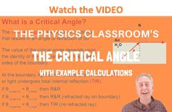
- a light ray is in the more dense medium and approaching the less dense medium.
- the angle of incidence for the light ray is greater than the so-called critical angle.
In our introduction to TIR, we used the example of light traveling through water towards the boundary with a less dense material such as air. When the angle of incidence in water reaches a certain critical value, the refracted ray lies along the boundary, having an angle of refraction of 90-degrees. This angle of incidence is known as the critical angle; it is the largest angle of incidence for which refraction can still occur. For any angle of incidence greater than the critical angle, light will undergo total internal reflection.
The Critical Angle Derivation
So the critical angle is defined as the angle of incidence that provides an angle of refraction of 90-degrees. Make particular note that the critical angle is an angle of incidence value. For the water-air boundary, the critical angle is 48.6-degrees. For the crown glass-water boundary, the critical angle is 61.0-degrees. The actual value of the critical angle is dependent upon the combination of materials present on each side of the boundary.
Let's consider two different media - creatively named medium i (incident medium) and medium r (refractive medium). The critical angle is the Θ i that gives a Θ r value of 90-degrees. If this information is substituted into Snell's Law equation, a generic equation for predicting the critical angle can be derived. The derivation is shown below.
n i • sine(Θ crit ) = n r • sine(90 degrees)
n i • sine(Θ crit ) = n r
sine(Θ crit ) = n r /n i
Θ crit = sine -1 (n r /n i ) = invsine (n r /n i )
The critical angle can be calculated by taking the inverse-sine of the ratio of the indices of refraction. The ratio of n r /n i is a value less than 1.0. In fact, for the equation to even give a correct answer, the ratio of n r /n i must be less than 1.0. Since TIR only occurs if the refractive medium is less dense than the incident medium, the value of n i must be greater than the value of n r . If at any time the values for the numerator and denominator become accidentally switched, the critical angle value cannot be calculated. Mathematically, this would involve finding the inverse-sine of a number greater than 1.00 - which is not possible. Physically, this would involve finding the critical angle for a situation in which the light is traveling from the less dense medium into the more dense medium - which again, is not possible.
This equation for the critical angle can be used to predict the critical angle for any boundary, provided that the indices of refraction of the two materials on each side of the boundary are known. Examples of its use are shown below:
The solution to the problem involves the use of the above equation for the critical angle.
Θ crit = sin -1 (1.000/1.52) = 41.1 degrees
Θ crit = sin -1 (1.000/2.42) = 24.4 degrees
TIR and the Sparkle of Diamonds
Relatively speaking, the critical angle for the diamond-air boundary is an extremely small number. Of all the possible combinations of materials that could interface to form a boundary, the combination of diamond and air provides one of the largest differences in the index of refraction values. This means that there will be a very small n r /n i ratio and subsequently a small critical angle. This peculiarity about the diamond-air boundary plays an important role in the brilliance of a diamond gemstone. Having a small critical angle, light has the tendency to become "trapped" inside of a diamond once it enters. A light ray will typically undergo TIR several times before finally refracting out of the diamond. Because the diamond-air boundary has such a small critical angle (due to diamond's large index of refraction), most rays approach the diamond at angles of incidence greater than the critical angle. This gives diamond a tendency to sparkle. The effect can be enhanced by the cutting of a diamond gemstone with a strategically planned shape. The diagram below depicts the total internal reflection within a diamond gemstone with a strategic and a non-strategic cut.
Practice Makes Perfect!
Use the Find the Critical Angle widget below to investigate the effect of the indices of refraction upon the critical angle. Simply enter the index of refraction values; then click the Calculate button to view the result. Use the widget as a practice tool.
Check Your Understanding
1. Suppose that the angle of incidence of a laser beam in water and heading towards air is adjusted to 50-degrees. Use Snell's law to calculate the angle of refraction? Explain your result (or lack of result).
Good luck! This problem has no solution. The angle of incidence is greater than the critical angle, so TIR occurs. There is no angle of refraction.
2. Aaron Agin is trying to determine the critical angle of the diamond-glass surface. He looks up the index of refraction values of diamond (2.42) and crown glass (1.52) and then tries to compute the critical angle by taking the
Unfortunately, Aaron's calculator keeps telling him he has an ERROR! Aaron hits the calculator and throws it own the ground a few times; he then repeats the calculation with the same result. He then utters something strange about the pizza he had slopped on it the evening before and runs out of the library with a disappointed disposition. What is Aaron's problem? (That is, what is the problem with his method of calculating the critical angle?)
Poor Aaron! It's not your pizza that's causing the problem; its your inappropriate use of the equation. You will need to take the inverse sine of the ratio (1.52 / 2.42). You have switched your numerator and denominator.
3. Calculate the critical angle for an ethanol-air boundary. Refer to the table of indices of refraction if necessary.
Θ crit = sine -1 (n i / n r )
Θ crit = sine -1 (1.0 / 1.36)
Θ crit = 47.3 degrees
4. Calculate the critical angle for a flint glass-air boundary. Refer to the table of indices of refraction if necessary.
Θ crit = sine -1 (1.0 / 1.58)
Θ crit = 39.3 degrees
5. Calculate the critical angle for a diamond-crown glass boundary. Refer to the table of indices of refraction if necessary.
Θ crit = sine -1 (1.52 / 2.42)
Θ crit = 38.9 degrees
6. Some optical instruments, such as periscopes and binoculars use trigonal prisms instead of mirrors to reflect light around corners. Light typically enters perpendicular to the face of the prism, undergoes TIR off the opposite face and then exits out the third face. Why do you suppose the manufacturer prefers the use of prisms instead of mirrors?
A prism will allow light to undergo total internal reflection whereas a mirror allows light to both reflect and refract. So for a prism, 100 percent of the light is reflected. But for a mirror, only about 95 percent of the light is reflected. For these reasons, a prism will produce a brighter image due to the greater percent of light being reflected.
- Dispersion of Light by Prisms
16.2 Refraction
Section learning objectives.
By the end of this section, you will be able to do the following:
- Explain refraction at media boundaries, predict the path of light after passing through a boundary (Snell’s law), describe the index of refraction of materials, explain total internal reflection, and describe applications of refraction and total internal reflection
- Perform calculations based on the law of refraction, Snell’s law, and the conditions for total internal reflection
Teacher Support
The learning objectives in this section help your students master the following standards:
- (D) investigate behaviors of waves, including reflection, refraction, diffraction, interference, resonance, and the Doppler effect; and
- (F) describe the role of wave characteristics and behaviors in medical and industrial applications.
In addition, the High School Physics Laboratory Manual addresses content in this section in the lab titled: Mirrors and Lenses, as well as the following standards:
- (D) investigate behaviors of waves, including reflection, refraction, diffraction, interference, resonance, and the Doppler effect.
Section Key Terms
The law of refraction.
[BL] [OL] Remind students that the maximum speed of light is its speed in a vacuum. This is a fundamental constant of physics. The maximum speed of light is equal to 3.00 × × 10 8 m/s. Have your students memorize this value.
You may have noticed some odd optical phenomena when looking into a fish tank. For example, you may see the same fish appear to be in two different places ( Figure 16.16 ). This is because light coming to you from the fish changes direction when it leaves the tank and, in this case, light rays traveling along two different paths both reach our eyes. The changing of a light ray’s direction (loosely called bending ) when it passes a boundary between materials of different composition, or between layers in single material where there are changes in temperature and density, is called refraction . Refraction is responsible for a tremendous range of optical phenomena, from the action of lenses to voice transmission through optical fibers.
[BL] An angle is the measure of the separation of two lines or rays originating from a single point. The length of the lines is not relevant.
[OL] [AL] The trigonometric function sine (sin) for a given angle is the ratio of the side of a right triangle opposite that angle to the hypotenuse of that triangle.
Why does light change direction when passing from one material (medium) to another? It is because light changes speed when going from one material to another. This behavior is typical of all waves and is especially easy to apply to light because light waves have very small wavelengths, and so they can be treated as rays. Before we study the law of refraction, it is useful to discuss the speed of light and how it varies between different media.
The speed of light is now known to great precision. In fact, the speed of light in a vacuum, c , is so important, and is so precisely known, that it is accepted as one of the basic physical quantities, and has the fixed value
where the approximate value of 3.00 × × 10 8 m/s is used whenever three-digit precision is sufficient. The speed of light through matter is less than it is in a vacuum, because light interacts with atoms in a material. The speed of light depends strongly on the type of material, given that its interaction with different atoms, crystal lattices, and other substructures varies. We define the index of refraction , n , of a material to be
where v is the observed speed of light in the material. Because the speed of light is always less than c in matter and equals c only in a vacuum, the index of refraction (plural: indices of refraction) is always greater than or equal to one.
Table 16.2 lists the indices of refraction in various common materials.
Figure 16.17 provides an analogy for and a description of how a ray of light changes direction when it passes from one medium to another. As in the previous section, the angles are measured relative to a perpendicular to the surface at the point where the light ray crosses it. The change in direction of the light ray depends on how the speed of light changes. The change in the speed of light is related to the indices of refraction of the media involved. In the situations shown in Figure 16.17 , medium 2 has a greater index of refraction than medium 1. This difference in index of refraction means that the speed of light is less in medium 2 than in medium 1. Note that, in Figure 16.17 (a), the path of the ray moves closer to the perpendicular when the ray slows down. Conversely, in Figure 16.17 (b), the path of the ray moves away from the perpendicular when the ray speeds up. The path is exactly reversible. In both cases, you can imagine what happens by thinking about pushing a lawn mower from a footpath onto grass, and vice versa. Going from the footpath to grass, the right front wheel is slowed and pulled to the side as shown. This is the same change in direction for light when it goes from a fast medium to a slow one. When going from the grass to the footpath, the left front wheel moves faster than the others, and the mower changes direction as shown. This, too, is the same change in direction as light going from slow to fast.
Bent Pencil
A classic observation of refraction occurs when a pencil is placed in a glass filled halfway with water. Do this and observe the shape of the pencil when you look at it sideways through air, glass, and water.
- A full-length pencil
- A glass half full of water
Instructions
- Place the pencil in the glass of water.
- Observe the pencil from the side.
- Explain your observations.
Look up the refractive indices of air, glass, and water in Table 16.2 . Think about how a ray of light changes direction for these transitions: air to glass and glass to water.
Virtual Physics
Bending light.
The Bending Light simulation allows you to show light refracting as it crosses the boundaries between various media (download animation first to view). It also shows the reflected ray. You can move the protractor to the point where the light meets the boundary and measure the angle of incidence, the angle of refraction , and the angle of reflection. You can also insert a prism into the beam to view the spreading, or dispersion , of white light into colors, as discussed later in this section. Use the ray option at the upper left.
- The medium below the boundary must have a greater index of refraction than the medium above.
- The medium below the boundary must have a lower index of refraction than the medium above.
- The medium below the boundary must have an index of refraction of zero.
- The medium above the boundary must have an infinite index of refraction.
Have students try all the different tabs at the top of the simulation. Point out to students that, although the tools work in both Ray and Wave mode, some may be easier to use in Wave mode because the region where the tool is able to read is larger.
[BL] Be sure students understand that if c is always greater than v , n must always be greater than one. Demonstrating division using numbers that can be divided easily can reinforce student understanding.
[OL] Explain that, unlike the law of reflection, the law of refraction is most easily expressed as an equation, rather than in words. Walk students through the lawnmower analogy in Figure 16.17 . Suggest other wheeled vehicles with which they may be more familiar, and other surfaces, such as sand.
[AL] Ask students to try to explain why a prism separates white light into a rainbow of colors, but a window pane does not. If they cannot explain it, show them a ray diagram of light transmitted through a flat sheet of glass.
The amount that a light ray changes direction depends both on the incident angle and the amount that the speed changes. For a ray at a given incident angle, a large change in speed causes a large change in direction, and thus a large change in the angle of refraction. The exact mathematical relationship is the law of refraction, or Snell’s law , which is stated in equation form as
In terms of speeds, Snell’s law becomes
Here, n 1 and n 2 are the indices of refraction for media 1 and 2, respectively, and θ 1 and θ 2 are the angles between the rays and the perpendicular in the respective media 1 and 2, as shown in Figure 16.17 . The incoming ray is called the incident ray and the outgoing ray is called the refracted ray . The associated angles are called the angle of incidence and the angle of refraction . Later, we apply Snell’s law to some practical situations.
Dispersion is defined as the spreading of white light into the wavelengths of which it is composed. This happens because the index of refraction varies slightly with wavelength. Figure 16.18 shows how a prism disperses white light into the colors of the rainbow.
Rainbows are produced by a combination of refraction and reflection. You may have noticed that you see a rainbow only when you turn your back to the Sun. Light enters a drop of water and is reflected from the back of the drop, as shown in Figure 16.19 . The light is refracted both as it enters and as it leaves the drop. Because the index of refraction of water varies with wavelength, the light is dispersed and a rainbow is observed.
Watch Physics
This video explains how refraction disperses white light into its composite colors.
- Colors with a longer wavelength and higher frequency bend most when refracted.
- Colors with a shorter wavelength and higher frequency bend most when refracted.
- Colors with a shorter wavelength and lower frequency bend most when refracted.
- Colors with a longer wavelength and a lower frequency bend most when refracted.
Have students note that the dependence of the index of refraction on the speed of light implies a dependence on wavelength, as discussed in the video. This is because v = f λ v = f λ for light in a medium. Different wavelengths of light travel at different speeds, and so refract differently at media boundaries. Also, have students note that the frequency of light is not affected by refraction; it remains constant.
A good-quality mirror reflects more than 90 percent of the light that falls on it; the mirror absorbs the rest. But, it would be useful to have a mirror that reflects all the light that falls on it. Interestingly, we can produce total reflection using an aspect of refraction. Consider what happens when a ray of light strikes the surface between two materials, such as is shown in Figure 16.20 (a). Part of the light crosses the boundary and is refracted; the rest is reflected. If, as shown in the figure, the index of refraction for the second medium is less than the first, the ray bends away from the perpendicular. Because n 1 > n 2 , the angle of refraction is greater than the angle of incidence—that is, θ 2 θ 2 > θ 1 θ 1 . Now, imagine what happens as the incident angle is increased. This causes θ 2 θ 2 to increase as well. The largest the angle of refraction, θ 2 θ 2 , can be is 90°, as shown in Figure 16.20 (b). The critical angle , θ c θ c , for a combination of two materials is defined to be the incident angle, θ 1 θ 1 , which produces an angle of refraction of 90°. That is, θ c θ c is the incident angle for which θ 2 θ 2 = 90°. If the incident angle, θ 1 θ 1 , is greater than the critical angle, as shown in Figure 16.20 (c), then all the light is reflected back into medium 1, a condition called total internal reflection .
Recall that Snell’s law states the relationship between angles and indices of refraction. It is given by
When the incident angle equals the critical angle ( θ 1 θ 1 = θ c θ c ), the angle of refraction is 90° ( θ 2 θ 2 = 90°). Noting that sin 90° = 1, Snell’s law in this case becomes
The critical angle, θ c θ c , for a given combination of materials is thus
for n 1 > n 2 .
[OL] The superscript in sin −1 is not a power. It indicates arcsine, which is an inverse trigonometric function. It means, “that angle whose sine equals (in this case) ( n 2 / n 1 ).”
Total internal reflection occurs for any incident angle greater than the critical angle, θ c θ c , and it can only occur when the second medium has an index of refraction less than the first. Note that the previous equation is written for a light ray that travels in medium 1 and reflects from medium 2, as shown in Figure 16.20 .
There are several important applications of total internal reflection. Total internal reflection, coupled with a large index of refraction, explains why diamonds sparkle more than other materials. The critical angle for a diamond-to-air surface is only 24.4°; so, when light enters a diamond, it has trouble getting back out ( Figure 16.21 ). Although light freely enters the diamond at different angles, it can exit only if it makes an angle less than 24.4° with the normal to a given surface. Facets on diamonds are specifically intended to make this unlikely, so that the light can exit only in certain places. Diamonds with very few impurities are very clear, so the light makes many internal reflections and is concentrated at the few places it can exit—hence the sparkle.
A light ray that strikes an object that consists of two mutually perpendicular reflecting surfaces is reflected back exactly parallel to the direction from which it came. This parallel reflection is true whenever the reflecting surfaces are perpendicular, and it is independent of the angle of incidence. Such an object is called a corner reflector because the light bounces from its inside corner. Many inexpensive reflector buttons on bicycles, cars, and warning signs have corner reflectors designed to return light in the direction from which it originates. Corner reflectors are perfectly efficient when the conditions for total internal reflection are satisfied. With common materials, it is easy to obtain a critical angle that is less than 45°. One use of these perfect mirrors is in binoculars, as shown in Figure 16.22 . Another application is for periscopes used in submarines.
Fiber optics are one common application of total internal reflection. In communications, fiber optics are used to transmit telephone, internet, and cable TV signals, and they use the transmission of light down fibers of plastic or glass. Because the fibers are thin, light entering one is likely to strike the inside surface at an angle greater than the critical angle and, thus, be totally reflected ( Figure 16.23 ). The index of refraction outside the fiber must be smaller than inside, a condition that is satisfied easily by coating the outside of the fiber with a material that has an appropriate refractive index. In fact, most fibers have a varying refractive index to allow more light to be guided along the fiber through total internal reflection. Rays are reflected around corners as shown in the figure, making the fibers into tiny light pipes .
Links To Physics
Medicine: endoscopes.
A medical device called an endoscope is shown in Figure 16.24 .
The word endoscope means looking inside . Doctors use endoscopes to look inside hollow organs in the human body and inside body cavities. These devices are used to diagnose internal physical problems. Images may be transmitted to an eyepiece or sent to a video screen. Another channel is sometimes included to allow the use of small surgical instruments. Such surgical procedures include collecting biopsies for later testing, and removing polyps and other growths.
- The process is refraction of light.
- The process is dispersion of light.
- The process is total internal reflection of light.
- The process is polarization of light.
Calculations with the Law of Refraction
[BL] If an equation has two variables and a constant, such as n = c / v , n = c / v , the value of only one variable is needed to find the other.
[OL] Explain the difference between sine and arcsine. Explain why sin 90° = 1. Note that the index of refraction is a dimensionless number.
[AL] Show why the values sin 0°, sin 30°, sin 45°, sin 60°, and sin 90° can be expressed in the form
Show that the numerical values of these expressions are 0, 0.5, 0.707, 0.866, and 1.00, respectively.
The calculation problems that follow require application of the following equations:
These are the equations for refractive index, the mathematical statement of the law of refraction (Snell’s law), and the equation for the critical angle.
Snell’s Law Example 1
This video leads you through calculations based on the application of the equation that represents Snell’s law.
- The two types of variables are density of a material and the angle made by the light ray with the normal.
- The two types of variables are density of a material and the thickness of a material.
- The two types of variables are refractive index and thickness of each material.
- The two types of variables are refractive index of a material and the angle made by a light ray with the normal.
Worked Example
Calculating index of refraction from speed.
Calculate the index of refraction for a solid medium in which the speed of light is 2.012 × × 10 8 m/s, and identify the most likely substance, based on the previous table of indicies of refraction.
We know the speed of light, c , is 3.00 × × 10 8 m/s, and we are given v . We can simply plug these values into the equation for index of refraction, n .
This value matches that of polystyrene exactly, according to the table of indices of refraction ( Table 16.2 ).
The three-digit approximation for c is used, which in this case is all that is needed. Many values in the table are only given to three significant figures. Note that the units for speed cancel to yield a dimensionless answer, which is correct.
Calculating Index of Refraction from Angles
Suppose you have an unknown, clear solid substance immersed in water and you wish to identify it by finding its index of refraction. You arrange to have a beam of light enter it at an angle of 45.00°, and you observe the angle of refraction to be 40.30°. What are the index of refraction of the substance and its likely identity?
We must use the mathematical expression for the law of refraction to solve this problem because we are given angle data, not speed data.
The subscripts 1 and 2 refer to values for water and the unknown, respectively, where 1 represents the medium from which the light is coming and 2 is the new medium it is entering. We are given the angle values, and the table of indicies of refraction gives us n for water as 1.333. All we have to do before solving the problem is rearrange the equation
The best match from Table 16.2 is fused quartz, with n = 1.458.
Note the relative sizes of the variables involved. For example, a larger angle has a larger sine value. This checks out for the two angles involved. Note that the smaller value of θ 2 θ 2 compared with θ 1 θ 1 indicates the ray has bent toward normal. This result is to be expected if the unknown substance has a greater n value than that of water. The result shows that this is the case.
Calculating Critical Angle
Verify that the critical angle for light going from water to air is 48.6°. (See Table 16.2 , the table of indices of refraction.)
First, choose the equation for critical angle
Then, look up the n values for water, n 1 , and air, n 2 . Find the value of n 2 n 1 n 2 n 1 . Last, find the angle that has a sine equal to this value and it compare with the given angle of 48.6°.
For water, n 1 = 1.333; for air, n 2 = 1.0003. So,
Remember, when we try to find a critical angle, we look for the angle at which light can no longer escape past a medium boundary by refraction. It is logical, then, to think of subscript 1 as referring to the medium the light is trying to leave, and subscript 2 as where it is trying (unsuccessfully) to go. So water is 1 and air is 2.
Practice Problems
The refractive index of ethanol is 1.36. What is the speed of light in ethanol?
- 2.25×10⁸ m/s
- 2.21×10⁷ m/s
- 2.25×10⁹ m/s
- 2.21×10⁸ m/s
Check Your Understanding
Use these questions to assess student achievement of the section’s learning objectives. If students are struggling with a specific objective, these questions help identify which one, and then you can direct students to the relevant content.
- This is Ohm’s law.
- This is Wien’s displacement law.
- This is Snell’s law.
- This is Newton’s law.
- The formula for index of refraction, n , of a material is n = speed of light in a material speed of light in a vacuum = v c , where \text{c}"> v > c , so n is always greater than one.
- The formula for index of refraction, n , of a material is n = speed of light in a vacuum speed of light in a material = c v , where \text{v}"> c > v , so n is always greater than one.
- The formula for index of refraction, n , of a material is n = speed of light in a vacuum × speed of light in a materaial = c × v , where c , 1"> v > 1 , so n is always greater than one.
- The formula for refractive index, n , of a material is n = 1 speed of light in a vacuum × speed of light in a material = 1 c × v , where "> c < v < 1 , so n is always greater than one.
- n 1 n 2 = sin θ 1 sin θ 2
- n 2 n 1 = ( sin θ 2 sin θ 1 ) 2
- n 1 n 2 = ( sin θ 2 sin θ 1 ) 2
- n 1 n 2 = sin θ 2 sin θ 1
This book may not be used in the training of large language models or otherwise be ingested into large language models or generative AI offerings without OpenStax's permission.
Want to cite, share, or modify this book? This book uses the Creative Commons Attribution License and you must attribute Texas Education Agency (TEA). The original material is available at: https://www.texasgateway.org/book/tea-physics . Changes were made to the original material, including updates to art, structure, and other content updates.
Access for free at https://openstax.org/books/physics/pages/1-introduction
- Authors: Paul Peter Urone, Roger Hinrichs
- Publisher/website: OpenStax
- Book title: Physics
- Publication date: Mar 26, 2020
- Location: Houston, Texas
- Book URL: https://openstax.org/books/physics/pages/1-introduction
- Section URL: https://openstax.org/books/physics/pages/16-2-refraction
© Jun 7, 2024 Texas Education Agency (TEA). The OpenStax name, OpenStax logo, OpenStax book covers, OpenStax CNX name, and OpenStax CNX logo are not subject to the Creative Commons license and may not be reproduced without the prior and express written consent of Rice University.
NOTIFICATIONS
Refraction of light.
- + Create new collection
Refraction is the bending of light (it also happens with sound, water and other waves) as it passes from one transparent substance into another.
This bending by refraction makes it possible for us to have lenses, magnifying glasses, prisms and rainbows. Even our eyes depend upon this bending of light. Without refraction, we wouldn’t be able to focus light onto our retina.
Change of speed causes change of direction
Light refracts whenever it travels at an angle into a substance with a different refractive index (optical density).
This change of direction is caused by a change in speed. For example, when light travels from air into water, it slows down, causing it to continue to travel at a different angle or direction.
How much does light bend?
The amount of bending depends on two things:
- Change in speed – if a substance causes the light to speed up or slow down more, it will refract (bend) more.
- Angle of the incident ray – if the light is entering the substance at a greater angle, the amount of refraction will also be more noticeable. On the other hand, if the light is entering the new substance from straight on (at 90° to the surface), the light will still slow down, but it won’t change direction at all.
Refractive index of some transparent substances
All angles are measured from an imaginary line drawn at 90° to the surface of the two substances This line is drawn as a dotted line and is called the normal.
If light enters any substance with a higher refractive index (such as from air into glass) it slows down. The light bends towards the normal line.
If light travels enters into a substance with a lower refractive index (such as from water into air) it speeds up. The light bends away from the normal line.
A higher refractive index shows that light will slow down and change direction more as it enters the substance.
A lens is simply a curved block of glass or plastic. There are two kinds of lens.
A biconvex lens is thicker at the middle than it is at the edges. This is the kind of lens used for a magnifying glass. Parallel rays of light can be focused in to a focal point. A biconvex lens is called a converging lens.
A biconcave lens curves is thinner at the middle than it is at the edges. Light rays refract outwards (spread apart) as they enter the lens and again as they leave.
Refraction can create a spectrum
Isaac Newton performed a famous experiment using a triangular block of glass called a prism. He used sunlight shining in through his window to create a spectrum of colours on the opposite side of his room.
This experiment showed that white light is actually made of all the colours of the rainbow. These seven colours are remembered by the acronym ROY G BIV – red, orange, yellow, green, blue, indigo and violet.
Newton showed that each of these colours cannot be turned into other colours. He also showed that they can be recombined to make white light again.
The explanation for the colours separating out is that the light is made of waves. Red light has a longer wavelength than violet light. The refractive index for red light in glass is slightly different than for violet light. Violet light slows down even more than red light, so it is refracted at a slightly greater angle.
The refractive index of red light in glass is 1.513. The refractive index of violet light is 1.532. This slight difference is enough for the shorter wavelengths of light to be refracted more.
A rainbow is caused because each colour refracts at slightly different angles as it enters, reflects off the inside and then leaves each tiny drop of rain.
A rainbow is easy to create using a spray bottle and the sunshine. The centre of the circle of the rainbow will always be the shadow of your head on the ground.
The secondary rainbow that can sometimes be seen is caused by each ray of light reflecting twice on the inside of each droplet before it leaves. This second reflection causes the colours on the secondary rainbow to be reversed. Red is at the top for the primary rainbow, but in the secondary rainbow, red is at the bottom.
Activity ideas
Use these activities with your students to explore refration further:
- Investigating refraction and spearfishing – students aim spears at a model of a fish in a container of water. When they move their spears towards the fish, they miss!
- Angle of refraction calculator challenge – students choose two types of transparent substance. They then enter the angle of the incident ray in the spreadsheet calculator, and the angle of the refracted ray is calculated for them.
- Light and sight: true or false? – students participate in an interactive ‘true or false’ activity that highlights common alternative conceptions about light and sight. This activity can be done individually, in pairs or as a whole class .
Useful links
Learn more about different types of rainbows, how they are made and other atmospheric optical phenomena with this MetService blog and Science Kids post .
Learn more about human lenses, optics, photoreceptors and neural pathways that enable vision through this tutorial from Biology Online .
See our newsletters here .
Would you like to take a short survey?
This survey will open in a new tab and you can fill it out after your visit to the site.
Thank you for visiting nature.com. You are using a browser version with limited support for CSS. To obtain the best experience, we recommend you use a more up to date browser (or turn off compatibility mode in Internet Explorer). In the meantime, to ensure continued support, we are displaying the site without styles and JavaScript.
- View all journals
- My Account Login
- Explore content
- About the journal
- Publish with us
- Sign up for alerts
- Open access
- Published: 11 September 2024
Observing the two-dimensional Bose glass in an optical quasicrystal
- Jr-Chiun Yu 1 , 2 ,
- Shaurya Bhave ORCID: orcid.org/0009-0006-9465-5025 1 ,
- Lee Reeve 1 ,
- Bo Song ORCID: orcid.org/0000-0002-5495-8308 1 , 3 &
- Ulrich Schneider ORCID: orcid.org/0000-0003-4345-9498 1
Nature volume 633 , pages 338–343 ( 2024 ) Cite this article
60 Altmetric
Metrics details
- Phase transitions and critical phenomena
- Ultracold gases
The presence of disorder substantially influences the behaviour of physical systems. It can give rise to slow or glassy dynamics, or to a complete suppression of transport as in Anderson insulators 1 , where normally extended wavefunctions such as light fields or electronic Bloch waves become exponentially localized. The combined effect of disorder and interactions is central to the richness of condensed-matter physics 2 . In bosonic systems, it can also lead to additional quantum states such as the Bose glass 3 , 4 —an insulating but compressible state without long-range phase coherence that emerges in disordered bosonic systems and is distinct from the well-known superfluid and Mott insulating ground states of interacting bosons. Here we report the experimental realization of the two-dimensional Bose glass using ultracold atoms in an eight-fold symmetric quasicrystalline optical lattice 5 . By probing the coherence properties of the system, we observe a Bose-glass-to-superfluid transition and map out the phase diagram in the weakly interacting regime. We furthermore demonstrate that it is not possible to adiabatically traverse the Bose glass on typical experimental timescales by examining the capability to restore coherence and discuss the connection to the expected non-ergodicity of the Bose glass. Our observations are in good agreement with recent quantum Monte Carlo predictions 6 and pave the way for experimentally testing the connection between the Bose glass, many-body localization and glassy dynamics more generally 7 , 8 .
Crystallization of bosonic quantum Hall states in a rotating quantum gas

Bloch oscillations and matter-wave localization of a dipolar quantum gas in a one-dimensional lattice

Bosonic stimulation of atom–light scattering in an ultracold gas
The interplay between disorder and interaction is central to the richness of condensed-matter physics as any real-life material will inevitably contain a certain degree of impurities and defects, and interparticle interactions are almost always present. While disorder tends to localize non-interacting particles, leading to Anderson localization 1 , interactions can counteract this, resulting in conducting ergodic states. More generally, the combination of disorder and interactions gives rise to rich physics governed by reduced or absent relaxation and transport, such as glassy dynamics or non-ergodic many-body localized systems, and forms one of the central topics in quantum statistical physics during the past decade 2 .
In bosonic systems, a hallmark of this interplay is the emergence of an additional ground-state phase called Bose glass. The Bose glass is an insulating but compressible phase without long-range phase coherence 3 , 4 . It was originally discussed purely as a ground state at zero temperature, but has been shown to extend to finite energy 9 , 10 , 11 , 12 . In the weakly interacting regime, the Bose glass can be understood by starting from a non-interacting Anderson insulator, where in the ground state all bosons localize at the lowest potential minimum (Fig. 1c ). Adding small repulsive interactions to such systems will lead to bosons spilling over into other low-lying orbitals to minimize the interaction energy. This regime has also been referred to as an Anderson glass or Lifshitz glass 13 , 14 . With increasing interactions or density, and thereby increasing chemical potential, these originally isolated orbitals will form local superfluid puddles that will eventually merge into a global superfluid phase.

a , The 2D quasicrystalline optical lattice is generated by superimposing four independent 1D lattices in the x – y plane, marked by small arrows. A deep z lattice (large arrows) divides the system into a series of independent quasi-2D layers. b , Exemplary potential in a single layer. c , Repulsive interactions can delocalize an originally localized disordered system. From top to bottom, the sketches show the transition of the system’s ground state with increasing chemical potential μ , starting from the Anderson insulator (AI) in the non-interacting limit ( μ = ϵ 0 = 0), where the disorder strength Δ is above the critical disorder strength for localization Δ c , over the localized but compressible Bose glass (BG) for weak repulsive interactions where bosons spill over into other low-lying minima and form local superfluid puddles, into the superfluid (SF) when the chemical potential is comparable to or larger than the disorder strength Δ .
As the lowest-lying minima are typically located arbitrarily far away from each other, any changes or relaxation processes that require redistribution of particles between these distant minima may, in localized phases, require arbitrarily long times. In the non-interacting Anderson limit, orbitals localized at different local minima can indeed possess arbitrarily close energies while having only exponentially weak couplings 15 , thus resulting in many almost degenerate levels. This absence of level repulsion is a hallmark of non-ergodic phases 16 , 17 . As a consequence of these exponentially small gaps, even rather slow parameter changes within the Bose glass could be expected to take the system out of equilibrium.
In fact, although local changes within a localized system can induce changes over distances that are large compared with the localization length, the characteristic distance could be shown to increase only logarithmically with time and thus directly leads to exponentially large timescales in large systems 18 . Therefore, the thermodynamic notion of quasistatic or adiabatic changes, where the system remains in thermal equilibrium at all times and the process is isentropic, may not apply. This is reminiscent of many-body localization (MBL) 2 and opens the question to which degree the Bose glass can be seen as the low-energy limit of a more general potential bosonic MBL phase.
Disordered interacting bosons have been studied for instance using helium-4 in porous media 19 , Cooper pairs in superconducting films 20 and disordered quantum magnets 21 . In the context of ultracold atoms, the Bose glass has been extensively studied using various numerical methods 22 , 23 , 24 , 25 , 26 , 27 , 28 , 29 , 30 . Previous experiments in one dimension have shown the loss of coherence but were strongly affected by finite-temperature effects 31 , 32 , 33 , 34 , 35 and experiments in three dimensions using speckle disorder studied momentum and quench responses 36 , 37 .
In this work, we investigate the low-energy states of a weakly interacting Bose gas in a two-dimensional (2D) eight-fold rotationally symmetric quasicrystalline optical lattice 5 . By analysing the momentum distribution of the system, we observe the Bose-glass-to-superfluid phase transition, and map out the phase diagram in the weakly interacting regime. Furthermore, our work experimentally establishes the non-adiabatic nature of the Bose glass, thereby highlighting its continuous connection to potential bosonic MBL phases at finite energy density 7 , 8 .
A 2D quasicrystalline optical lattice
Quasicrystals are long-range ordered yet not periodic 38 , 39 and thereby represent a fascinating middle ground between order and disorder. In contrast to purely random potentials, where in one and two dimensions all single-particle eigenstates are localized for any non-vanishing disorder 40 , quasiperiodic potentials support a phase transition from extended to exponentially localized states at a finite potential depth 41 , 42 , thus providing an ideal platform for studying disorder-induced phenomena.
In our experiment, we load a degenerate Bose gas of about 1.2 × 10 5 potassium 39 K atoms without discernible thermal fraction into a 2D quasicrystalline optical lattice using a 45-ms-long exponential ramp ( Methods ). The optical quasicrystal is formed by superimposing four independent blue-detuned one-dimensional (1D) lattices in the x – y plane at 45° angles, as depicted schematically in Fig. 1a . Each of these lattices is a 1D standing wave created by a retro-reflected laser beam at wavelength λ lat = 725.4 nm. In addition, a deep lattice along the direction perpendicular to the plane ( z axis) effectively slices the system into an array of 2D layers (see the grey disks in Fig. 1a ). The resulting potential is given by
where V 0 and V z denote the lattice depths, and k i and k z are the respective wavevectors ( \(|{{\bf{k}}}_{i}|={k}_{z}={k}_{{\rm{l}}{\rm{a}}{\rm{t}}}=2{\rm{\pi }}/{\lambda }_{{\rm{l}}{\rm{a}}{\rm{t}}}\) ) of the four 1D lattices in the x – y plane and the z lattice. The phase offsets ϕ i are central to describe phasonic degrees of freedom and topological pumping in these potentials, but have no significant role in localization in large systems 43 .
Throughout this work, the depths of the horizontal lattices are varied in the range of V 0 = 1–4 E rec and the z lattice is kept at V z = 20 E rec , where \({E}_{{\rm{rec}}}={\hbar }^{2}{k}_{{\rm{lat}}}^{2}/(2m)\) is the recoil energy, ħ is the reduced Planck constant and m is the atomic mass. The deep z lattice provides a sufficiently strong vertical confinement so that interlayer tunnelling is negligible. As a consequence, atoms loaded into the lattice will be tightly confined to individual quasi-2D systems that show an eight-fold symmetric quasicrystalline structure, as depicted in Fig. 1b . A red-detuned dipole trap ( Methods ) provides an overall harmonic confinement and gives rise to an inhomogeneous density distribution (Fig. 2c ).

a , TOF images (9 ms TOF, 5 shots averaged) for different scattering lengths a at a fixed lattice depth of V 0 = 2.8 E rec . Although the system is localized in the non-interacting and very weakly interacting cases, the appearance of sharp interference peaks for stronger interactions signals the emergence of long-range phase coherence, characteristic for the superfluid. b , Width of the central peak, distinguishing the coherent superfluid (light blue) from the incoherent Bose glass (dark blue). The dashed line is a guide to the eye indicating the detected phase boundary in the centre of the cloud \({V}_{{\rm{loc}}}^{(a)}\) . It is identical to the line shown in the inset and in Fig. 3d . White points and error bars denote the QMC prediction from ref. 6 ( Methods ). Images in a correspond to the parameters marked by red diamonds. The inset shows the condensate fraction f c extracted from the same set of images, highlighting the coexistence of the two phases. c , Phase transition in an inhomogeneous system. The shaded Gaussian denotes the in-trap atomic density and the parabola represents the external trapping potential. For shallow lattices, the ground state is purely superfluid (left). At the non-interacting critical depth \({V}_{{\rm{loc}}}^{(0)}\) , the Bose glass starts to appear at the low-density edge of the cloud where interaction effects are small (middle). With increasing lattice depth, the phase boundary gradually moves inwards until the entire cloud enters the Bose glass phase at \({V}_{{\rm{loc}}}^{(a)}\) (right).
Even though the lattice depths used for the 2D quasicrystalline lattice are rather low, the physics of the system is nonetheless captured by a dedicated quasiperiodic Bose–Hubbard (QBH) model 43 , which in second quantization reads
Here \({\widehat{a}}_{i}^{\dagger }\) ( \({\widehat{a}}_{i}\) ) is the bosonic creation (annihilation) operator on the i th lattice site, and \({\widehat{n}}_{i}={\widehat{a}}_{i}^{\dagger }{\widehat{a}}_{i}\) is the corresponding number operator. The Hamiltonian \({\widehat{H}}_{{\rm{QBH}}}\) is characterized by three site-dependent parameters, namely, on-site energies ϵ i (neglecting the harmonic confinement), tunnelling energies J i j and on-site interactions U i ∝ a , whose scale can be independently controlled by tuning the atomic s-wave scattering length a by means of a Feshbach resonance ( Methods ). We set \({{\epsilon }}_{0}:= \min \,{{\epsilon }}_{i}=0\) and use \(\varDelta := \max \,{{\epsilon }}_{i}\) as an intuitive measure of ‘disorder strength’, even though the modulation in J i j and U i also influences the physics.
In the weakly interacting regime, systems described by the Hamiltonian \({\widehat{H}}_{{\rm{QBH}}}\) host a phase transition from Bose glass to superfluid, as illustrated in Fig. 1c . At strong interactions with U ≫ J , they furthermore host commensurate Mott insulators 6 , 43 ; however, this regime is not probed in the current paper ( Methods ). In this strongly interacting regime, the term Bose glass was introduced to describe the phase emerging when the charge order of the Mott insulator vanishes for strong enough disorder Δ ≈ U (refs. 25 , 29 ). This regime shows the same phenomenology as the weakly interacting Bose glass, namely being a compressible, gapless, insulating phase without long-range coherence, and hence they both belong to the Bose glass phase.
Phase diagram
Our main observable to distinguish superfluid and localized states is the momentum distribution detected using time-of-flight (TOF) imaging, that is, by releasing the atomic cloud from all trapping potentials and imaging its density distribution after 9 ms of free expansion. This can be understood as a matter-wave diffraction experiment where waves originating on different lattice sites expand, overlap and then interfere. Analogous to diffraction experiments in optics and in periodic lattices 44 , 45 , the coherence length, which quantifies the range of spatial coherence between lattice sites, determines the width of the matter-wave interference peaks. A high-contrast interference pattern composed of sharp peaks indicates the presence of long-range phase coherence, the signature of the superfluid phase. Localized states with only short-range coherence, however, result in an incoherent broad momentum distribution.
Figure 2a shows a series of TOF images recorded for different scattering lengths at a fixed lattice depth of V 0 = 2.8 E rec . At this lattice depth, the single-particle ground state is strongly localized 46 , and the measured momentum distribution at vanishing scattering length (top-left panel) correspondingly shows the broad momentum profile of a localized Anderson insulator. With increasing interactions, however, we observe the emergence of initially faint but sharp interference peaks, signalling the phase transition from the incoherent Bose glass to a superfluid in the high-density core of the cloud. The remaining broad background corresponds to the incoherent Bose glass at lower densities, where the critical lattice depth is lower and approaches the non-interacting limit.
To quantitatively study this transition at the high-density centre of the cloud, we choose an observable that can detect the presence of even a small superfluid component, namely, the full-width at half-maximum (FWHM) of the central peak. The FWHM, extracted from 2D Gaussian fits, provides an almost binary signature: if there exists a superfluid component, the FWHM corresponds to the width of the superfluid peak, which is dominated by the in situ cloud size 47 ( Methods ). Only when the superfluid completely vanishes, the FWHM jumps to the width of the incoherent background ( Methods and Extended Data Fig. 3 ).
The resulting phase diagram for the centre of the trap is shown in Fig. 2b and clearly reveals two distinct phases: the coherent superfluid at shallow lattices (light blue) turns relatively abruptly into the incoherent Bose glass (dark blue) at an interaction-dependent critical lattice depth \({V}_{{\rm{loc}}}^{(a)}\) . At vanishing scattering length, the observed \({V}_{{\rm{loc}}}^{(0)}\) coincides with the known single-particle localization point at around \({V}_{{\rm{loc}}}^{(0)}=1.78(2)\,{E}_{{\rm{rec}}}\) (refs. 41 , 46 ) up to minor corrections ( ≲ 1 a 0 , where a 0 denotes Bohr's radius) stemming from the presence of weak residual interactions due to small dipole–dipole interactions 48 and calibration uncertainties ( Methods ). With increasing scattering lengths, the critical lattice depth \({V}_{{\rm{loc}}}^{(a)}\) indicated by the dashed line shifts considerably towards deeper lattices, directly demonstrating that even weak repulsive interactions can significantly counteract localization. The observed transition agrees well with the recent quantum Monte Carlo (QMC) simulations for the ground state reported in ref. 6 . These low localization thresholds also imply large tunnelling energies 43 and hence a high resilience to temperature. Therefore, the expected effects 11 of the finite experimental temperature (<20 nK; Methods ) would be at most on the order of the QMC error bars.
As a complementary observable that highlights the inhomogeneous nature of the system, the inset of Fig. 2b shows the same phase diagram analysed in terms of the condensate fraction \({f}_{{\rm{c}}}:= {{\mathcal{N}}}_{{\rm{coh}}}\,/{\mathcal{N}}\) , that is, the number of atoms in the sharp interference peaks \({{\mathcal{N}}}_{{\rm{coh}}}\) divided by the total atom number \({\mathcal{N}}={{\mathcal{N}}}_{{\rm{coh}}}+{{\mathcal{N}}}_{{\rm{incoh}}}\) , where \({{\mathcal{N}}}_{{\rm{incoh}}}\) represents the population of the incoherent background (see Methods for details). The condensate fraction is high for shallow lattices and begins to slowly decrease after the lattice depth exceeds the non-interacting critical depth \({V}_{{\rm{loc}}}^{(0)}\) (see also Fig. 3e ). This initially small downwards trend gradually becomes stronger, and the condensate fraction eventually reaches zero at the same critical depth \({V}_{{\rm{loc}}}^{(a)}\) extracted from the FWHM measurement (dashed line).

a , Condensate fraction in the 2D quasicrystal (normalized within each plot) as a function of lattice depth for different loading durations and scattering lengths. Although 15-ms ramps result in consistently lower condensate fractions, there is no consistent difference between 30 ms and longer ramps. b , FWHM of the central peak ( w r ) after a linear ramp of duration τ from the 2D quasicrystal into a regular 3D cubic lattice, where the ground state is a superfluid. The coloured circles correspond to different depths of the quasicrystalline potential V 0 for a fixed scattering length of a = 10 a 0 . For \({V}_{0} < {V}_{{\rm{loc}}}^{(10)}\) (blue circles), the initial state in the quasicrystal is superfluid and the final states show strong superfluid order for all explored ramp times. For a deep Bose glass at \({V}_{0} > {V}_{{\rm{loc}}}^{(10)}\) (red circles), in contrast, there is no initial coherence and only a very limited degree of phase coherence can be restored, demonstrating the absence of adiabatic evolution into and out of the Bose glass. c , An equivalent measurement for a Mott insulator in a regular 3D cubic lattice ( V x , y , z = 16 E rec , a = 150 a 0 ). Although the initial state also lacks coherence, it can be rapidly restored by ramping down the lattice depth in τ ≳ 2 ms. Insets in b and c show TOF images and OD denotes the optical density. d , Phase diagram showing w r for a slow ramp with τ = 15 ms highlighting three different regimes: a pure superfluid (light blue), an intermediate regime where superfluid and Bose glass coexist in the trap, and finally the pure Bose glass (darker blues). The transition into the pure Bose glass is consistent with the phase boundary extracted in Fig. 2b (dashed line). e , Comparing condensate fraction f c in the quasicrystal with w r for a = 23 a 0 , demonstrating the consistency of all observations. The dashed line denotes the critical lattice depth \({V}_{{\rm{loc}}}^{(23)}\) extracted from the main diagram of Fig. 2b and the grey area indicates the intermediate regime where superfluid and Bose glass coexist. The solid lines in b , c and e are guides to the eye.
The gradual decrease in the condensate fraction is consistent with the expected coexistence of superfluid and Bose glass in the system. This is the result of the inhomogeneous atomic density caused by the background harmonic dipole trap, as illustrated in Fig. 2c : when atoms are loaded into the lattice, the low-density edge of the cloud, where interaction effects vanish, will start to localize at the critical depth for non-interacting atoms \({V}_{{\rm{loc}}}^{(0)}\) (ref. 37 ). As we further increase the lattice depth, the phase boundary that separates the Bose glass from the superfluid core will slowly move towards higher densities until all atoms are ultimately in the Bose glass phase.
Absence of adiabaticity at the Bose glass transition
In typical quantum phase transitions between ergodic phases, for example, from superfluid to Mott insulator 45 , an important experimental check is whether the phase transition was crossed adiabatically, and thereby reversibly, or whether the observed loss of coherence results from irreversible heating, due to, for instance, rapid non-adiabatic changes that generate entropy. In the present case, however, the situation is potentially rather different, as the Bose glass is expected to be non-ergodic such that the thermodynamic notion of adiabatic changes may not apply.
To investigate this, we first study in Fig. 3a the effect of different lattice loading durations on the resulting condensate fraction. A too-rapid lattice ramp (15 ms) gives rise to considerable heating already in the superfluid regime, leading to lower condensate fractions compared with slower ramps. Once the loading duration exceeds 30 ms, it however becomes irrelevant and the condensate fraction is independent of the loading rate, demonstrating adiabaticity within the superfluid and consistent critical lattice depths \({V}_{{\rm{loc}}}^{(a)}\) .
To study whether the phase transition was crossed adiabatically, we next try to restore superfluid coherence. Here we first load the atoms into the 2D quasicrystalline lattice in 45 ms, and then continuously transform the non-periodic lattice into a periodic simple-cubic three-dimensional (3D) lattice. This transformation is carried out by linearly ramping the depth of the x , y and z lattices to 8 E rec over various durations τ while simultaneously reducing the depth of the remaining two diagonal lattices (Fig. 1a ) to zero. The 3D cubic lattice was chosen as in this lattice the ground state is a superfluid with a finite critical temperature for condensation for all studied parameters 49 .
Figure 3b shows the FWHM of the central peak, w r , in the final periodic lattice for different ramp times τ at a fixed scattering length ( a = 10 a 0 ), and the outcome highlights the fundamentally distinct behaviours of the superfluid and Bose glass phases. For \({V}_{0} < {V}_{{\rm{loc}}}^{(10)}\) (blue circles), the system remained superfluid during the entire sequence, and the ground state can adapt rapidly from a quasiperiodic extended wave to a periodic Bloch wave, as indicated by the sharp and narrow diffraction peaks for all ramp durations. For \({V}_{0} > {V}_{{\rm{loc}}}^{(10)}\) (red circles), however, where the system has entered the Bose glass regime, the initial state contains only very short-range coherence and hence results in a high w r . Furthermore, the measured w r remains significantly above that of the superfluid even for the slowest ramps explored in this measurement. This demonstrates that the system in this regime can restore only a very limited degree of phase coherence and thereby directly highlights the significant entropy production arising from traversing, that is, entering, ramping through and exiting the Bose glass. In combination, the above measurements demonstrate that despite the loading duration becoming irrelevant for sufficiently slow ramps, it remains impossible to traverse the Bose glass isentropically, that is, in a thermodynamically adiabatic fashion.
To show that the reduced coherence is not solely caused by dynamical effects such as Kibble–Zurek-type dynamics 47 during too-fast final ramps, Figure 3c shows an equivalent measurement starting from a Mott insulator in a deep 3D simple-cubic lattice, where phase coherence is recovered by reducing the lattice potential to the same final depth as in the previous case. In this case, sharp interference patterns can be recovered already within 2 ms of ramp-down time, consistent with previous observations 45 , 47 . This contrast not only experimentally confirms that the incoherent localized phase we observe in the optical quasicrystal is distinct from a Mott insulator but also highlights that the inability to traverse the Bose glass adiabatically is rather distinct from the critical slowing down expected at conventional continuous phase transitions 46 , 47 . It is consistent with glassy dynamics in general and the expected non-ergodic nature of the Bose glass in particular.
Figure 3d shows the FWHM of the central peak ( w r ) after a slow final ramp of τ = 15 ms and demonstrates that the observed breakdown of adiabaticity indeed coincides with the transition into the Bose glass. This is further corroborated by the cuts shown in Fig. 3e : as more and more atoms localize and enter the Bose glass, not only does the condensate fraction decrease but also the coherence cannot be restored.
In this work, we experimentally study the 2D Bose glass in an optical quasicrystal with eight-fold rotational symmetry by probing the coherence properties of the system. We directly observe the phase transition between the Bose glass and the superfluid, in good agreement with QMC simulations 6 . In addition, we study the possibility to traverse the Bose glass adiabatically and always find significant entropy increases that are consistent with the expected non-ergodic character of the Bose glass. This paves the way for testing the connection between the Bose glass, MBL and glassy dynamics more generally. Quasicrystalline and quasiperiodic lattices offer a unique route to study MBL, as their long-range ordered nature can exclude conventional ergodic rare regions 41 , 50 that are expected to destabilize MBL by seeding thermalization avalanches in real random systems 51 , 52 .
Experimental sequence
The experimental sequence begins with loading an almost pure Bose–Einstein condensate of about 1.2 × 10 5 39 K atoms without discernible thermal fraction from a red-detuned crossed optical dipole trap ( λ dip = 1,064 nm, with trap frequencies ( ω x , ω y , ω z ) = 2π × (55, 43, 330) Hz) into a blue-detuned 2D quasiperiodic optical lattice ( λ lat = 725.4 nm). The initial temperature is bounded from above by T i < 20 nK due to a conservative lower bound on the observed condensate fraction. Even neglecting that temperatures for weakly interacting bosons typically decrease when loading into a lattice, the resulting change in critical chemical potential Δ μ due to the finite temperature is small according to ref. 11 , that is, Δ μ / μ < 2.5% or, equivalently, Δ μ /( μ − ϵ 0 ) < 20%, where \({{\epsilon }}_{0}:= \min \,{{\epsilon }}_{i}\) . During the loading, the individual lattice depths are increased in 45 ms from 0 to their target values using exponential ramps with a time constant of 10 ms. The used target depths for the four horizontal lattices range within V 0 = 1–4 E rec while a fixed depth of V z = 20 E rec for the vertical z lattice ensures the formation of well-defined quasi-2D systems. After this ramp, the atoms are held in the quasicrystal for 10 ms. For imaging, we apply a short ‘booster stage’ 53 before we switch off all trapping potentials and record the matter-wave interference pattern by taking an absorption image after 9 ms TOF.
The booster stage consists of linearly increasing the potential depth of the horizontal lattices in 40 μs to a final depth of V final = 6 E rec . This stage is sufficiently short to not change the coherence properties of the system while providing a tighter on-site confinement and thereby not only enhancing the brightness of high-order diffraction peaks but also significantly reducing the heavy saturation on the central momentum peak (Extended Data Fig. 1a,b ).
The interaction strengths U i ∝ a are independently controlled by tuning the atomic s-wave scattering length ( a ) using the Feshbach resonance close to 403 G of the \(| F=1,{m}_{F}=1\rangle \) state in 39 K (refs. 54 , 55 ). Here F denotes the total angular momentum and m F denotes the magnetic quantum number of the state. To ensure broadly comparable density distributions, the scattering length is initially prepared at a common finite value of a = 12 a 0 before the lattice loading starts and is then changed using a 20 ms linear current ramp to the desired value within a = 0–30 a 0 starting after the first 5 ms of the lattice ramp. Subsequently, the scattering length remains constant until being suddenly switched to a = 0 a 0 at the beginning of the TOF.
A periodic cubic 3D lattice can be produced by using only two orthogonal 1D lattices ( x , y ) out of the four in-plane 1D lattices indicated in Fig. 1 as well as the perpendicular z lattice. This was used as the final lattice in the attempt to restore superfluid coherence. For the final lattice depths in Fig. 3b–e , the ground state in the cubic lattice is a superfluid for all studied interactions. Although the cubic lattice is a priori only one of several possible choices, ramping into a periodic 3D lattice has the advantage that it results in an ergodic system where long-range coherence emerges below a finite critical temperature 49 .
Furthermore, the same cubic lattice geometry was also used for preparing the initial Mott insulating state in Fig. 3c , where the restoration of phase coherence is then carried out by employing a 16–8 E rec linear ramp on all the three lattice axes simultaneously.
Coherence length and extraction of condensate fraction
In the TOF images, the width of the sharp diffraction peaks of the superfluid is dominated by the finite initial cloud size, which in combination with the finite TOF acts as an effective resolution limit for the measured momentum distribution 47 . Therefore, no significant broadening is expected as long as the coherence lengths in the superfluid part remains above 3– 5 λ lat (ref. 47 ). In the inhomogeneous system, the FWHM of the central peak (compare Fig. 2b ) corresponds to this resolution-limited width as long as the k ≈ 0 peak of the superfluid remains visible atop the incoherent background of localized atoms. The FWHM jumps to the background width once the interference peaks have completely merged into the background, thereby giving rise to the sharp signature shown in Fig. 2b . This jump hence stems from the combination of the inhomogeneous system with the effective resolution limit imposed by the finite TOF and would not be present in a homogeneous system.
The condensate fraction f c is a complimentary observable that measures the fraction of coherent atoms and is evaluated for every shot according to \({f}_{{\rm{c}}}={{\mathcal{N}}}_{{\rm{coh}}}\,/{\mathcal{N}}\) , where \({{\mathcal{N}}}_{{\rm{coh}}}\) is the population in the sharp interference peaks, and \({\mathcal{N}}={{\mathcal{N}}}_{{\rm{coh}}}+{{\mathcal{N}}}_{{\rm{incoh}}}\) is the total atom number with \({{\mathcal{N}}}_{{\rm{incoh}}}\) being the number of atoms in the incoherent background.
To extract \({{\mathcal{N}}}_{{\rm{coh}}}={\sum }_{k}{n}_{k}\) from the TOF images, we first identify the most pronounced 81 diffraction peaks within the first six diffraction orders 5 and then extract their populations n k by fitting independent 2D Gaussian profiles to each peak. To prevent counting spurious populations from weakly populated peaks, we exclude fitted populations n k below 0.12% of the total atom number. Extended Data Fig. 1c illustrates the extracted populations.
The atom number in the incoherent background, \({{\mathcal{N}}}_{{\rm{incoh}}}\) , is acquired by performing an additional 2D Gaussian fit to the whole cloud (region of interest \(3.3\times 3.3\,{(\hbar {k}_{{\rm{lat}}})}^{2}\) ), where all detected diffraction peaks were masked during the fitting.
Parameter calibration
The two main experimental parameters are the lattice depth and the scattering length between atoms. The lattice depth is calibrated to within 0.1 E rec by analysing the dynamics of Kapitza–Dirac diffraction for each 1D lattice individually; see the supplementary material of ref. 5 for details.
The scattering length is calibrated by observing the prominent atom-loss features corresponding to the zero-crossing of the scattering length, where the in situ density is highest, and the Feshbach resonance, where the loss coefficient is maximal. We then interpolate the scattering length between them using the common functional form 55 , 56 . As an independent cross-check, the magnetic field is calibrated using radio-frequency spectroscopy of the \(| F=1,{m}_{F}=-1\rangle \) to \(| F=1,{m}_{F}=0\rangle \) transition in 87 Rb and converted to a scattering length using literature values for the parameters of the Feshbach resonance 55 , 56 . The two approaches agree to ≲ 1 a 0 .
Comparing with QMC simulations
The QMC calculations reported in ref. 6 were performed as a function of the density n in a homogeneous system at fixed interaction strength g . As the main panel of Fig. 2b focuses on the phase transition in the centre of the trap, we extract the experimental central density n 0 from in situ absorption images using the known aspect ratio of the trap. To minimize statistical noise, we measure n 0 at different scattering lengths ( a = 0–30 a 0 ) and constant lattice depth ( V 0 = 1 E rec ) and find a mild interaction dependence n 0 (30 a 0 ) ≈ 1/2 n 0 (0 a 0 ) for the used lattice ramp (Extended Data Fig. 2 ). In addition, we relate the 2D interaction coupling constant g used in ref. 6 back to the 3D scattering length a via
Here a lat = λ lat /2 and \({l}_{\perp }=\sqrt{\hbar /m{\omega }_{\perp }}\) is the characteristic confining length given by the strong z lattice with a trapping frequency of ω ⊥ = 2π × 87 kHz.
Excluding Mott insulators
To investigate the possibility of Mott insulators in our experiment, we numerically compute the Bose–Hubbard parameters of the quasiperiodic potential using the results from ref. 43 . We calculate the site-dependent ratio between on-site interactions and tunnelling energies \({U}_{i}/{\sum }_{j}| \,{J}_{ij}| \) , where the sum runs over all significant tunnelling elements linking site i to other adjacent sites. Within the explored parameter regime, this ratio reaches a maximum of \(\max ({U}_{i}/{\sum }_{j}| \,{J}_{ij}| )\approx 1.4\) for the case of a = 30 a 0 and V 0 = 4.0 E rec . This is significantly below the critical interaction strength for forming a Mott insulator in a 2D square lattice ( U / zJ ) c ≈ 4.385 (ref. 57 ), where z = 4 represents the number of nearest neighbours. Furthermore, the studied parameter range lies within the weakly interacting regime of ref. 11 , and Mott insulators can hence be excluded in this experiment.
Data availability
The data shown in this paper are available from https://doi.org/10.17863/CAM.111477 .
Anderson, P. W. Absence of diffusion in certain random lattices. Phys. Rev. 109 , 1492–1505 (1958).
Article ADS CAS Google Scholar
Abanin, D. A., Altman, E., Bloch, I. & Serbyn, M. Colloquium: Many-body localization, thermalization, and entanglement. Rev. Mod. Phys. 91 , 021001 (2019).
Article ADS MathSciNet CAS Google Scholar
Giamarchi, T. & Schulz, H. Anderson localization and interactions in one-dimensional metals. Phys. Rev. B 37 , 325–340 (1988).
Fisher, M. P., Weichman, P. B., Grinstein, G. & Fisher, D. S. Boson localization and the superfluid–insulator transition. Phys. Rev. B 40 , 546–570 (1989).
Viebahn, K., Sbroscia, M., Carter, E., Yu, J.-C. & Schneider, U. Matter-wave diffraction from a quasicrystalline optical lattice. Phys. Rev. Lett. 122 , 110404 (2019).
Article ADS CAS PubMed Google Scholar
Gautier, R., Yao, H. & Sanchez-Palencia, L. Strongly interacting bosons in a two-dimensional quasicrystal lattice. Phys. Rev. Lett. 126 , 110401 (2021).
Choi, J.-Y. et al. Exploring the many-body localization transition in two dimensions. Science 352 , 1547–1552 (2016).
Article ADS MathSciNet CAS PubMed Google Scholar
Bordia, P. et al. Probing slow relaxation and many-body localization in two-dimensional quasiperiodic systems. Phys. Rev. X 7 , 041047 (2017).
Google Scholar
Michal, V. P., Aleiner, I. L., Altshuler, B. L. & Shlyapnikov, G. V. Finite-temperature fluid–insulator transition of strongly interacting 1D disordered bosons. Proc. Natl Acad. Sci. USA 113 , E4455–E4459 (2016).
Article ADS CAS PubMed PubMed Central Google Scholar
Bertoli, G., Michal, V., Altshuler, B. & Shlyapnikov, G. Finite-temperature disordered bosons in two dimensions. Phys. Rev. Lett. 121 , 030403 (2018).
Zhu, Z., Yao, H. & Sanchez-Palencia, L. Thermodynamic phase diagram of two-dimensional bosons in a quasicrystal potential. Phys. Rev. Lett. 130 , 220402 (2023).
Ciardi, M., Macrì, T. & Cinti, F. Finite-temperature phases of trapped bosons in a two-dimensional quasiperiodic potential. Phys. Rev. A 105 , L011301 (2022).
Scalettar, R. T., Batrouni, G. G. & Zimanyi, G. T. Localization in interacting, disordered, Bose systems. Phys. Rev. Lett. 66 , 3144–3147 (1991).
Lugan, P. et al. Ultracold Bose gases in 1D disorder: from Lifshits glass to Bose–Einstein condensate. Phys. Rev. Lett. 98 , 170403 (2007).
Article ADS Google Scholar
Altshuler, B., Krovi, H. & Roland, J. Anderson localization makes adiabatic quantum optimization fail. Proc. Natl Acad. Sci. USA 107 , 12446–12450 (2010).
Oganesyan, V. & Huse, D. A. Localization of interacting fermions at high temperature. Phys. Rev. B 75 , 155111 (2007).
Pal, A. & Huse, D. A. Many-body localization phase transition. Phys. Rev. B 82 , 174411 (2010).
Khemani, V., Nandkishore, R. & Sondhi, S. L. Nonlocal adiabatic response of a localized system to local manipulations. Nat. Phys. 11 , 560–565 (2015).
Article CAS Google Scholar
Crowell, P. A., Van Keuls, F. W. & Reppy, J. D. Onset of superfluidity in 4 He films adsorbed on disordered substrates. Phys. Rev. B 55 , 12620–12634 (1997).
Sacépé, B. et al. Localization of preformed Cooper pairs in disordered superconductors. Nat. Phys. 7 , 239–244 (2011).
Article Google Scholar
Yu, R. et al. Bose glass and Mott glass of quasiparticles in a doped quantum magnet. Nature 489 , 379–384 (2012).
Rapsch, S., Schollwöck, U. & Zwerger, W. Density matrix renormalization group for disordered bosons in one dimension. Europhys. Lett. 46 , 559 (1999).
Roux, G. et al. Quasiperiodic Bose–Hubbard model and localization in one-dimensional cold atomic gases. Phys. Rev. A 78 , 023628 (2008).
Bissbort, U. & Hofstetter, W. Stochastic mean-field theory for the disordered Bose–Hubbard model. Europhys. Lett. 86 , 50007 (2009).
Söyler, Ş. G., Kiselev, M., Prokof’ev, N. V. & Svistunov, B. V. Phase diagram of the commensurate two-dimensional disordered Bose–Hubbard model. Phys. Rev. Lett. 107 , 185301 (2011).
Article ADS PubMed Google Scholar
Niederle, A. & Rieger, H. Bosons in a two-dimensional bichromatic quasiperiodic potential: analysis of the disorder in the Bose–Hubbard parameters and phase diagrams. Phys. Rev. A 91 , 043632 (2015).
Gerster, M. et al. Superfluid density and quasi-long-range order in the one-dimensional disordered Bose–Hubbard model. New J. Phys. 18 , 015015 (2016).
Yao, H., Giamarchi, T. & Sanchez-Palencia, L. Lieb–Liniger bosons in a shallow quasiperiodic potential: Bose glass phase and fractal Mott lobes. Phys. Rev. Lett. 125 , 060401 (2020).
Zhang, C., Safavi-Naini, A. & Capogrosso-Sansone, B. Equilibrium phases of two-dimensional bosons in quasiperiodic lattices. Phys. Rev. A 91 , 031604 (2015).
Johnstone, D., Öhberg, P. & Duncan, C. W. The mean-field Bose glass in quasicrystalline systems. J. Phys. A 54 , 395001 (2021).
Article MathSciNet Google Scholar
Gadway, B., Pertot, D., Reeves, J., Vogt, M. & Schneble, D. Glassy behavior in a binary atomic mixture. Phys. Rev. Lett. 107 , 145306 (2011).
Fallani, L., Lye, J., Guarrera, V., Fort, C. & Inguscio, M. Ultracold atoms in a disordered crystal of light: towards a Bose glass. Phys. Rev. Lett. 98 , 130404 (2007).
Deissler, B. et al. Delocalization of a disordered bosonic system by repulsive interactions. Nat. Phys. 6 , 354–358 (2010).
D’Errico, C. et al. Observation of a disordered bosonic insulator from weak to strong interactions. Phys. Rev. Lett. 113 , 095301 (2014).
Gori, L. et al. Finite-temperature effects on interacting bosonic one-dimensional systems in disordered lattices. Phys. Rev. A 93 , 033650 (2016).
Pasienski, M., McKay, D., White, M. & DeMarco, B. A disordered insulator in an optical lattice. Nat. Phys. 6 , 677–680 (2010).
Meldgin, C. et al. Probing the Bose glass–superfluid transition using quantum quenches of disorder. Nat. Phys. 12 , 646–649 (2016).
Shechtman, D., Blech, I., Gratias, D. & Cahn, J. W. Metallic phase with long-range orientational order and no translational symmetry. Phys. Rev. Lett. 53 , 1951 (1984).
Steurer, W. Quasicrystals: What do we know? What do we want to know? What can we know? Acta Crystallogr. A 74 , 1–11 (2018).
Article MathSciNet CAS Google Scholar
Abrahams, E., Anderson, P., Licciardello, D. & Ramakrishnan, T. Scaling theory of localization: absence of quantum diffusion in two dimensions. Phys. Rev. Lett. 42 , 673–676 (1979).
Szabó, A. & Schneider, U. Mixed spectra and partially extended states in a two-dimensional quasiperiodic model. Phys. Rev. B 101 , 014205 (2020).
Roati, G. et al. Anderson localization of a non-interacting Bose–Einstein condensate. Nature 453 , 895–898 (2008).
Gottlob, E. & Schneider, U. Hubbard models for quasicrystalline potentials. Phys. Rev. B 107 , 144202 (2023).
Pedri, P. et al. Expansion of a coherent array of Bose–Einstein condensates. Phys. Rev. Lett. 87 , 220401 (2001).
Greiner, M., Mandel, O., Esslinger, T., Hänsch, T. W. & Bloch, I. Quantum phase transition from a superfluid to a Mott insulator in a gas of ultracold atoms. Nature 415 , 39–44 (2002).
Sbroscia, M. et al. Observing localization in a 2D quasicrystalline optical lattice. Phys. Rev. Lett. 125 , 200604 (2020).
Braun, S. et al. Emergence of coherence and the dynamics of quantum phase transitions. Proc. Natl Acad. Sci. USA 112 , 3641–3646 (2015).
Wall, M. & Carr, L. Dipole–dipole interactions in optical lattices do not follow an inverse cube power law. New J. Phys. 15 , 123005 (2013).
Trotzky, S. et al. Suppression of the critical temperature for superfluidity near the Mott transition: validating a quantum simulator. Nat. Phys. 6 , 998–1004 (2009).
Štrkalj, A., Doggen, E. V. & Castelnovo, C. Coexistence of localization and transport in many-body two-dimensional Aubry–André models. Phys. Rev. B 106 , 184209 (2022).
De Roeck, W. & Huveneers, F. Stability and instability towards delocalization in many-body localization systems. Phys. Rev. B 95 , 155129 (2017).
Léonard, J. et al. Probing the onset of quantum avalanches in a many-body localized system. Nat. Phys . 19 , 481–485 (2023).
Stöferle, T., Moritz, H., Schori, C., Köhl, M. & Esslinger, T. Transition from a strongly interacting 1D superfluid to a Mott insulator. Phys. Rev. Lett. 92 , 130403 (2004).
d’Errico, C. et al. Feshbach resonances in ultracold 39 K. New J. Phys. 9 , 223 (2007).
Fletcher, R. J. et al. Two- and three-body contacts in the unitary Bose gas. Science 355 , 377–380 (2017).
Etrych, J. et al. Pinpointing Feshbach resonances and testing Efimov universalities in 39 K. Phys. Rev. Res. 5 , 013174 (2023).
Wessel, S., Alet, F., Troyer, M. & Batrouni, G. G. Quantum Monte Carlo simulations of confined bosonic atoms in optical lattices. Phys. Rev. A 70 , 053615 (2004).
Download references
Acknowledgements
We thank K. Viebahn, M. Sbroscia and E. Carter for their contributions to building the experimental set-up; and E. Gottlob, J. Thywissen and L. Sanchez-Palencia and his team for discussions. This work was supported by the European Commission ERC Starting Grant QUASICRYSTAL, the EPSRC Grant (number EP/R044627/1) and EPSRC Programme Grant DesOEQ (number EP/P009565/1).
Author information
Authors and affiliations.
Cavendish Laboratory, University of Cambridge, Cambridge, UK
Jr-Chiun Yu, Shaurya Bhave, Lee Reeve, Bo Song & Ulrich Schneider
Material and Chemical Research Laboratories, Industrial Technology Research Institute, Hsinchu, Taiwan
Jr-Chiun Yu
State Key Laboratory for Mesoscopic Physics and Frontiers Science Center for Nano-optoelectronics, School of Physics, Peking University, Beijing, China
You can also search for this author in PubMed Google Scholar
Contributions
U.S. conceived the project and J.-C.Y., S.B., L.R. and B.S. performed the experiments and analysed the data. All authors contributed to discussions and the editing of the paper.
Corresponding authors
Correspondence to Bo Song or Ulrich Schneider .
Ethics declarations
Competing interests.
The authors declare no competing interests.
Peer review
Peer review information.
Nature thanks Thierry Giamarchi, Giovanni Modugno and the other, anonymous, reviewer(s) for their contribution to the peer review of this work.
Additional information
Publisher’s note Springer Nature remains neutral with regard to jurisdictional claims in published maps and institutional affiliations.
Extended data figures and tables
Extended data fig. 1 effect of booster stage ( v 0 = 2 e rec , a = 10 a 0 ) and an example of the population extraction..
a , In the absence of the booster, the majority of condensed atoms remain in the central diffraction peak, with only a small fraction occupying the satellite peaks. The high atomic density of the central peak causes almost all the imaging light around this central area to be fully absorbed, leading to significant imaging saturation at k = 0. b , the booster stage promotes condensed atoms to higher diffraction orders, thus facilitating the fitting. c , Simulated diffraction pattern for the first 6 diffraction orders. The 81 peaks considered in the population count are coloured in blue, with their radius indicating the extracted population n k . Gray dots represent the peaks that can also be observed but are not included in the population count due to their low populations. Images in (a,b) are averaged over 30 experimental shots in order to visually emphasise the signal from very weakly populated high-order diffraction peaks.
Extended Data Fig. 2 Extraction of central density.
a , Central density as a function of scattering length. b , Fit to in-situ column density distribution used to extract the effective cloud width for calculating the central density. The employed absorption imaging starts to saturate for OD ≳ 2.5, hence, data points above this value (grey) have been excluded from the fit.
Extended Data Fig. 3 Width of central peak.
a , FWHM of central peak for a = 11 a 0 , data taken from Fig. 2b . b , Normalised cuts through the density distribution observed after time-of-flight (analogous to cuts through Fig. 2a ). The red line in a indicates the measured in-situ cloud size, demonstrating that the observed peak width is dominated by the in-situ size. Both the FWHM and the absence of thermal components around the peaks in b demonstrate that the momentum distribution is compatible with T = 0 up to very close to the phase transition. Red dots in upper panel indicate the lattice depths used in the lower panel.
Rights and permissions
Open Access This article is licensed under a Creative Commons Attribution 4.0 International License, which permits use, sharing, adaptation, distribution and reproduction in any medium or format, as long as you give appropriate credit to the original author(s) and the source, provide a link to the Creative Commons licence, and indicate if changes were made. The images or other third party material in this article are included in the article’s Creative Commons licence, unless indicated otherwise in a credit line to the material. If material is not included in the article’s Creative Commons licence and your intended use is not permitted by statutory regulation or exceeds the permitted use, you will need to obtain permission directly from the copyright holder. To view a copy of this licence, visit http://creativecommons.org/licenses/by/4.0/ .
Reprints and permissions
About this article
Cite this article.
Yu, JC., Bhave, S., Reeve, L. et al. Observing the two-dimensional Bose glass in an optical quasicrystal. Nature 633 , 338–343 (2024). https://doi.org/10.1038/s41586-024-07875-2
Download citation
Received : 05 May 2023
Accepted : 25 July 2024
Published : 11 September 2024
Issue Date : 12 September 2024
DOI : https://doi.org/10.1038/s41586-024-07875-2
Share this article
Anyone you share the following link with will be able to read this content:
Sorry, a shareable link is not currently available for this article.
Provided by the Springer Nature SharedIt content-sharing initiative
By submitting a comment you agree to abide by our Terms and Community Guidelines . If you find something abusive or that does not comply with our terms or guidelines please flag it as inappropriate.
Quick links
- Explore articles by subject
- Guide to authors
- Editorial policies
Sign up for the Nature Briefing newsletter — what matters in science, free to your inbox daily.

IMAGES
VIDEO
COMMENTS
When light rays interact with an entity, like a piece of glass, the electromagnetic wave causes the electron clouds in the material to vibrate; as the electron clouds vibrate, they regenerate the wave. This happens in a succession of "ripples" as the light passes through the object. Because this process takes time, that's why light slows down ...
3. The explanation is very simple! The reason light changes direction ("bends") when traveling through glass, is because light travels slower in glass than in air. If now, you also want to know why light travels slower in glass than air, it is because the density of glass is higher than air and the electromagnetic fields of the glass molecules ...
The important and interesting thing here is that the effect that we see as a slowing of a particle-- a photon taking a longer time to pass through glass than air-- is actually a collective effect ...
Assuming that light travels from air to glass, the angle of incidence is 30°, and the angle of refraction is 20°. To calculate the refractive index, follow these steps: Identify the refractive index of air: n ₁ = 1. Modify Snell's law to find the refractive index of glass: n ₂ = n ₁sin (θ₁)/sin (θ₂). Enter data: n ₂ = 1×sin (30 ...
The angle of incidence in the water is approximately 39°. At this angle, the light refracts out of the water into the surrounding air bending away from the normal. The angle of refraction in the air is approximately 57°. These values for the angle of incidence and refraction are consistent with Snell's Law.
Well, if you think light is a wave, it's easy to explain. Electromagnetic waves simply travel slower through glass than through air. So the wave crests are closer to each other, but the light still oscillates the same number of times per second. It stays the same color. When the wave hits the air again, its color still doesn't change, while the ...
Note: As the speed of light is at its maximum in vacuum, the absolute refractive index always greater than \(1\). Also note that the refractive index is a relative quantity and thus it had no units. Question: The absolute refractive index of a glass window is \(1.5\). What is the speed of light when it is traveling through the glass window?
The spectrum is produced because different colours of light travel at different speeds in glass.This means that each colour of light is refracted by a different amount when it enters the glass and ...
When light traveling in one transparent medium encounters a boundary with a second transparent medium (e.g., air and glass), a portion of the light is reflected and a portion is transmitted into the second medium. As the transmitted light moves into the second medium, it changes its direction of travel; that is, it is refracted.
Instead, they are absorbed by the atoms and/or electrons within the glass, which then emit new EM waves. The new EM waves emitted by the energised particles make up the forward-radiation, which is the light observed from the opposite side of the glass. So it appears as if light is travelling through the glass, but it's actually being absorbed ...
When light travels through a glass, the intensity of the light is typically reduced. This absorption happens when the energy of a photon of light matches the energy needed to excite an electron within the glass to its higher energy state, and the photon is absorbed by the glass. The absorption spectrum of a glass varies by composition.
The light travels along the optical fiber, reflecting off the walls of the fiber. With a straight or smoothly bending fiber, the light will hit the wall at an angle higher than the critical angle and will all be reflected back into the fiber. Even though the light undergoes a large number of reflections when traveling along a fiber, no light is ...
Explore bending of light between two media with different indices of refraction. See how changing from air to water to glass changes the bending angle. Play with prisms of different shapes and make rainbows.
24. This was discussed in an answer to a related question but I think that it deserves a separate and, hopefully, more clear answer. Consider a single photon (λ λ =532 nm) traveling through a plate of perfect glass with a refractive index n = 1.5 n = 1.5. We know that it does not change its direction or other characteristics in any particular ...
In the situations shown in Figure 25.3.3 25.3. 3, medium 2 has a greater index of refraction than medium 1. This means that the speed of light is less in medium 2 than in medium 1. Note that as shown in Figure 25.3.3a 25.3. 3 a, the direction of the ray moves closer to the perpendicular when it slows down.
Light travelling through a fibre can impart a twist to glass spheres without if the light itself is not twisting.
The eyedropper "disappears" because of how we see light as it encounters glass. When light hits a glass object, some of the light bounces (or reflects) off the glass. The rest of the light ...
The important and interesting thing here is that the effect that we see as a slowing of a particle- a photon taking a longer time to pass through glass than air- is actually a collective effect due to the wave nature of the photon. The path of the light is ultimately determined by an interference between parts of the photon wavefunction ...
a light ray is in the more dense medium and approaching the less dense medium. the angle of incidence for the light ray is greater than the so-called critical angle. In our introduction to TIR, we used the example of light traveling through water towards the boundary with a less dense material such as air.
A light wave travelling in air that is reflected by a glass barrier will undergo a 180° phase change, while light travelling in glass will not undergo a phase change if it is reflected by a boundary with air. For this reason, optical boundaries are normally specified as an ordered pair (air-glass, glass-air); indicating which material the ...
Example 11.4.1 11.4. 1: Speed of Light in Matter. Calculate the speed of light in zircon, a material used in jewelry to imitate diamond. Strategy: The speed of light in a material, v v, can be calculated from the index of refraction n n of the material using the equation n = c/v n = c / v. Solution.
Figure 16.16 Looking at the fish tank as shown, we can see the same fish in two different locations, because light changes directions when it passes from water to air. In this case, light rays traveling on two different paths change direction as they travel from water to air, and so reach the observer.
Red light has a longer wavelength than violet light. The refractive index for red light in glass is slightly different than for violet light. Violet light slows down even more than red light, so it is refracted at a slightly greater angle. The refractive index of red light in glass is 1.513. The refractive index of violet light is 1.532.
The two-dimensional Bose glass state of matter is realized experimentally using ultracold atoms in an eight-fold symmetric quasicrystalline optical lattice, and the phase transition between Bose ...